RL78/G15 CHAPTER 16 RESET FUNCTION
R01UH0959EJ0110 Rev.1.10 Page 639 of 765
Mar 7, 2023
16.2 States of Operation During Reset Periods
Table 16-1 shows the states of operation during reset periods. Table 16-2 shows the state of the hardware after
acceptance of a reset.
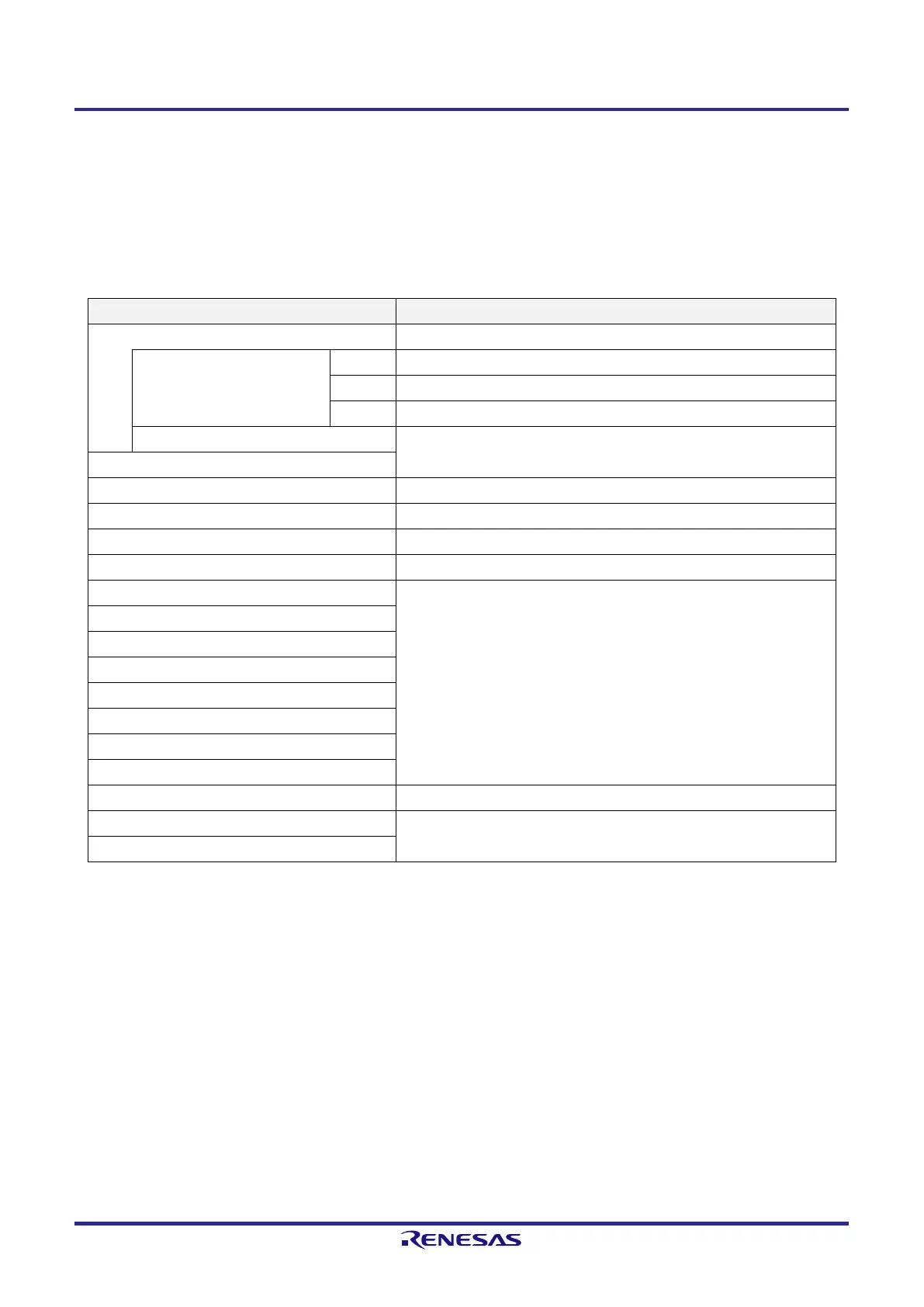
Table 16-1. States of Operation During Reset Period
Item During Reset Period
System clock Clock supply to the CPU is stopped.
Main system clock f
IH
Operation stopped
f
X
Note 1
Operation stopped (the X1 and X2 pins are input port mode)
f
EX
Note 1
Clock input invalid (the pin is input port mode)
f
IL
Operation stopped
CPU
Code flash memory Operation stopped
Data flash memory Operation stopped
RAM Operation stopped
Port (latch) High impedance
Note 2
Timer array unit Operation stopped
12-bit interval timer
Watchdog timer
Clock output/buzzer output
A/D converter
Comparator
Serial array unit (SAU)
Serial interface (IICA)
Selectable power-on-reset function Detection operation possible
External interrupt Operation stopped
Illegal-memory access detection function
Note 1. 16-pin and 20-pin products only.
Note 2. Statuses of P40 and P125 pins are as follows
P40
High-impedance during external reset period or reset period by the data retention power supply voltage.
High level during other types of reset or after receiving a reset (connected to the internal pull-up resistor).
P125
Low level during external reset period (low level input to RESET
¯¯¯¯¯¯
pin). High level during other types of reset
period or after receiving a reset (connected to the internal pull-up resistor).
Remark f
IH
: Highspeed on-chip oscillator clock
f
X
: X1 clock
f
EX
: External main system clock
f
IL
: Low-speed on-chip oscillator clock
 Loading...


