RL78/G15 CHAPTER 24 ELECTRICAL SPECIFICATIONS (T
A
= −40 to +105°C, TA = −40 to +125°C)
R01UH0959EJ0110 Rev.1.10 Page 736 of 765
Mar 7, 2023
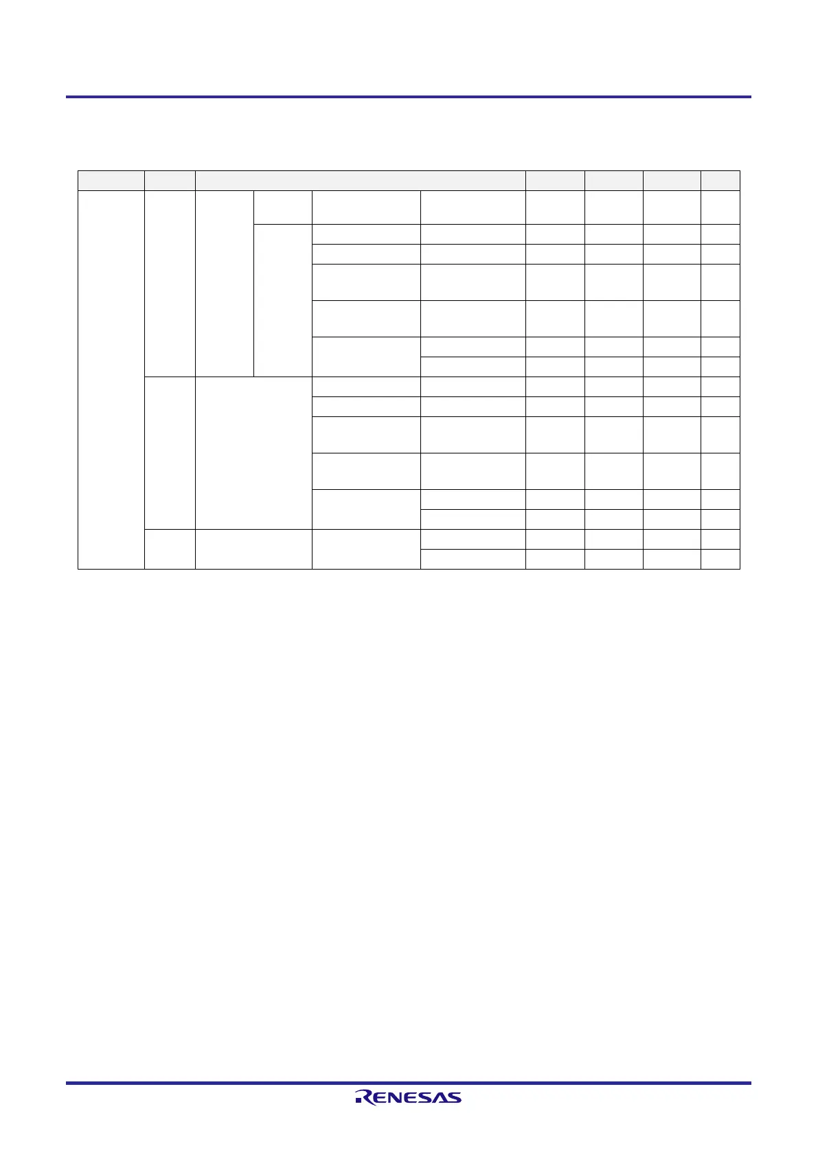
24.3.2 Supply current characteristics
[T
A
= −40 to +105°C: G products, T
A
= −40 to +125°C: M products, 2.4 V ≤ V
DD
≤ 5.5 V, V
SS
= 0 V]
Item Symbol Condition MIN. TYP. MAX. Unit
Supply
current
Note 1
I
DD1
Operating
mode
Basic
operation
f
IH
= 16 MHz
Note 4
V
DD
= 3.0 V, 5.0 V 0.87 mA
Normal
operation
f
IH
= 16 MHz
Note 4
V
DD
= 3.0 V, 5.0 V 1.86 2.49 mA
f
IH
= 4 MHz
Note 4
V
DD
= 3.0 V, 5.0 V 1.17 1.65 mA
f
EX
= 16 MHz
Note 5, Note 6
V
DD
= 3.0 V, 5.0 V
Square wave input 1.69 2.32 mA
f
X
= 12 MHz
Note 5, Note 6
V
DD
= 3.0 V, 5.0 V
Resonator connection 1.57 2.32 mA
f
MX
= 4 MHz
Note 5, Note 6
V
DD
= 3.0 V, 5.0 V
Square wave input 1.00 1.47 mA
Resonator connection 1.05 1.55 mA
I
DD2
Note 2
HALT mode f
IH
= 16 MHz
Note 4
V
DD
= 3.0 V, 5.0 V 371 811 µA
f
IH
= 4 MHz
Note 4
V
DD
= 3.0 V, 5.0 V 334 637 µA
f
EX
= 16 MHz
Note 5, Note 6
V
DD
= 3.0 V, 5.0 V
Square wave input 207 647 µA
f
X
= 12 MHz
Note 5, Note 6
V
DD
= 3.0 V, 5.0 V
Resonator connection 309 909 µA
f
MX
= 4 MHz
Note 5, Note 6
V
DD
= 3.0 V, 5.0 V
Square wave input 156 459 µA
Resonator connection 207 609 µA
I
DD3
Note 3
STOP mode V
DD
= 3.0 V T
A
= +105°C 0.62 3.71 µA
T
A
= +125°C 0.62 7.44 µA
Note 1. The listed currents are the total currents flowing into V
DD
, including the input leakage currents flowing when
the level of the input pin is fixed to V
DD
or V
SS
.
Regarding the values for main system clock operation, the TYP. value does not include the peripheral
operating current. The MAX. value includes the peripheral operating current, but does not include those
flowing into the A/D converter, comparator, I/O port, and on-chip pull-up/pull-down resistors.
Regarding the values for subsystem clock operation, the TYP. and MAX. values do not include the peripheral
operating current. However, in HALT mode, the current flowing into the RTC is included.
Regarding the values in STOP mode, the TYP. and MAX. values do not include the peripheral operating
current.
Note 2. When the HALT instruction is executed from the flash memory.
Note 3. The listed currents do not include the current flowing into the 12-bit interval timer and watchdog timer.
Note 4. When the high-speed subsystem clock is stopped.
Note 5. When the high-speed on-chip oscillator is stopped.
Note 6. 16-pin and 20-pin products only.
Remark 1. f
IH
: High-speed on-chip oscillator clock frequency
Remark 2. f
MX
: High-speed system clock frequency (X1 clock oscillation frequency or external main system clock
frequency)
Remark 3. The temperature condition of the TYP. value is T
A
= 25°C.
 Loading...


