RL78/G15 CHAPTER 6 TIMER ARRAY UNIT
R01UH0959EJ0110 Rev.1.10 Page 208 of 765
Mar 7, 2023
6.5.3 Operation of counter
Here, the counter operation in each mode is explained.
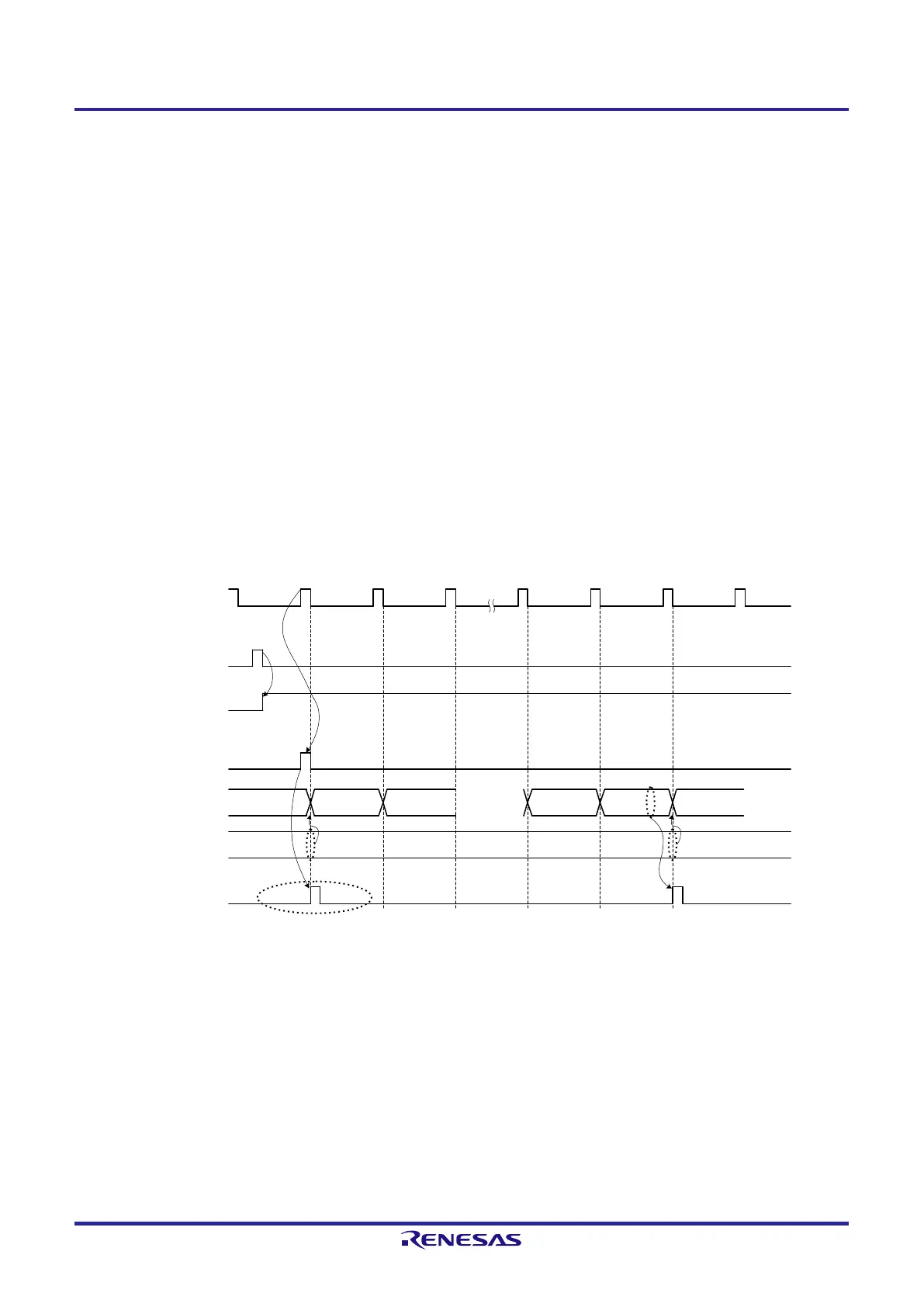
(1) Operation of interval timer mode
<1> Operation is enabled (TEmn = 1) by writing 1 to the TSmn bit. Timer count register mn (TCRmn) holds the initial
value until count clock generation.
<2> A start trigger is generated at the first count clock (f
MCK
) after operation is enabled.
<3> When the MDmn0 bit is set to 1, INTTMmn is generated by the start trigger.
<4> By the first count clock after the operation enable, the value of timer data register mn (TDRmn) is loaded to the
TCRmn register and counting starts in the interval timer mode.
<5> When the TCRmn register counts down and its count value is 0000H, INTTMmn is generated at the next count
clock (f
MCK
) and the value of timer data register mn (TDRmn) is loaded to the TCRmn register and counting
keeps on.
Figure 6-24. Operation Timing (In Interval Timer Mode)
f
MCK
(f
TCLK
)
When MDmn0 = 1 setting
<1>
<3>
<4>
0000 m0001
<2>
<5>
Initial value
m
m – 1
m
TSmn (Write)
TEmn
Start trigger
detection signal
TCRmn
TDRmn
INTTMmn
• • • • • • •
Caution In the first cycle operation of count clock after writing the TSmn bit, an error at a maximum of one
clock is generated since count start delays until count clock has been generated. When the
information on count start timing is necessary, an interrupt can be generated at count start by setting
MDmn0 = 1.
Remark f
MCK
, the start trigger detection signal, and INTTMmn become active between one clock in synchronization
with f
CLK
.
 Loading...


