RL78/G15 CHAPTER 13 SERIAL INTERFACE IICA
R01UH0959EJ0110 Rev.1.10 Page 531 of 765
Mar 7, 2023
13.5 I
2
C Bus Definitions and Control Methods
The following describes the serial data communication format of the I
2
C bus and the signals to be used.
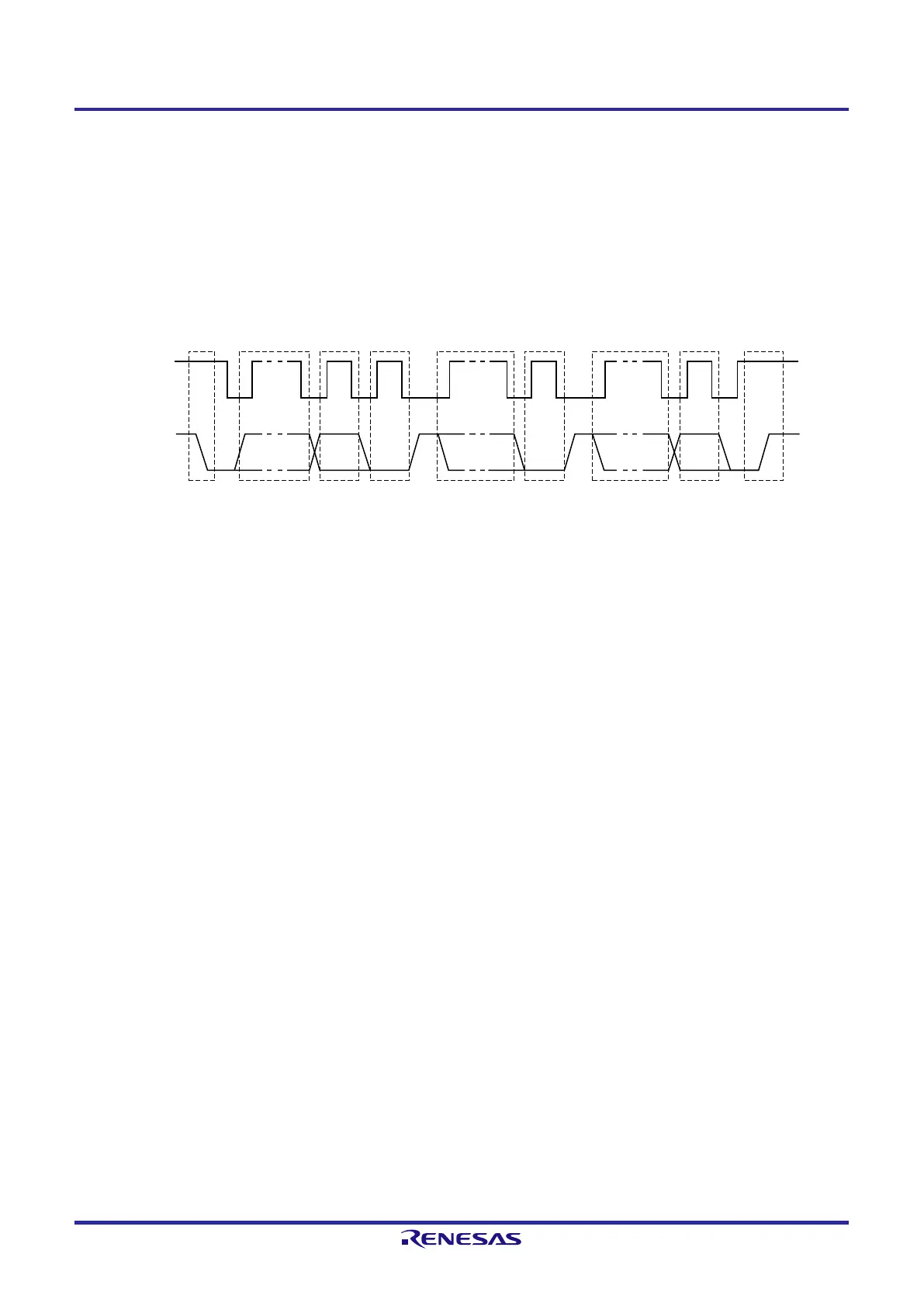
Figure 13-13 shows the timing of transfer of the “start condition”, “address”, “data”, and “stop condition” which are
generated on the serial data bus of the I
2
C bus.
Figure 13-13. I
2
C Bus Serial Data Transfer Timing
SCLA0
SDAA0
Start
condition
Address
__
R/W
ACK
Data
1
-7
8 9 1-8
Data
9 1-8 9
Stop
condition
ACK ACK
The master generates a start condition, slave address, and stop condition.
The acknowledge (ACK) can be generated by either the master or slave (normally, it is output by the receiver of 8-bit
data).
The serial clock (SCLA0) is continuously output by the master. However, for the slave, a low-level period of the SCLA0
pin can be extended and clock stretching can be inserted.
 Loading...


