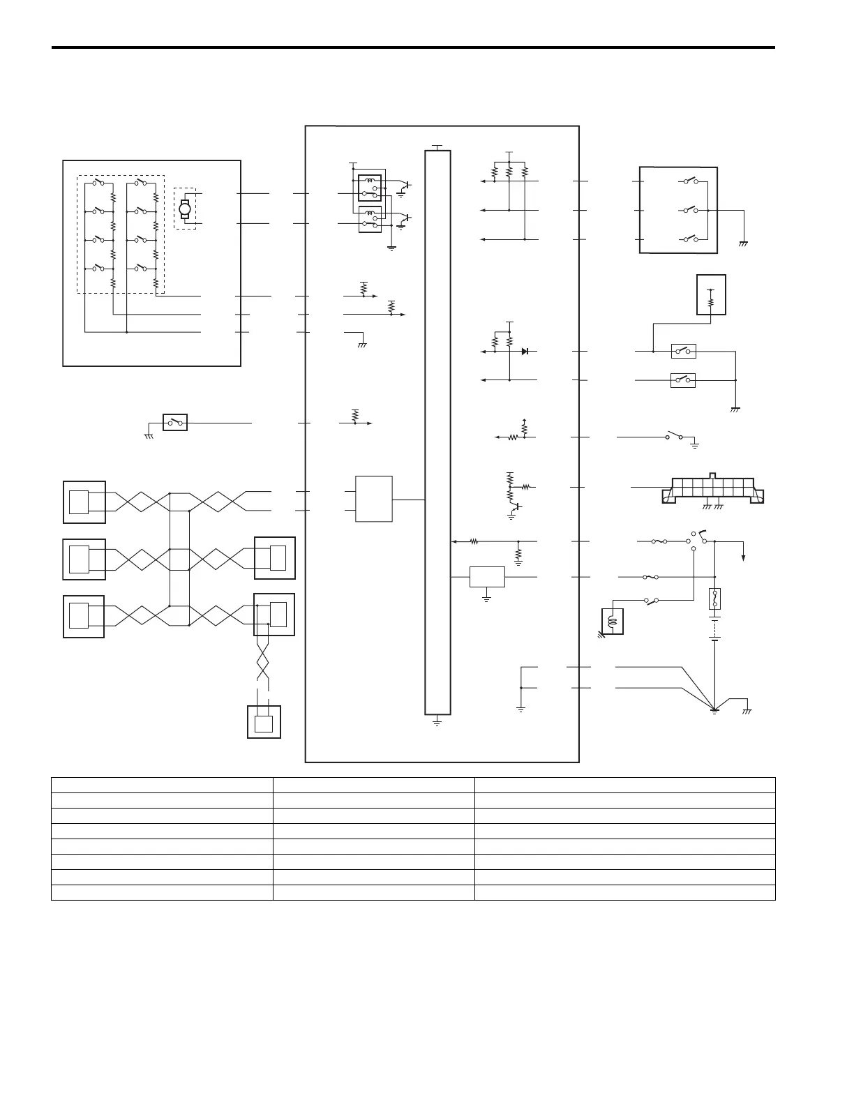
3C-11 Transfer: Motor-Shift Type (Transfer with Shift Actuator)
4WD Control System Wiring Circuit Diagram
S5JB0E3311006
5V
5V
IG
5V
12V
E91-2
5V
12V
12V
+BB
YEL
RED/BLK
BLU
M
E91-3
E91-25
E91-26
RED
E91-24
BLK/YEL
E91-7
BLK/ORN
E91-21
PPL/WHT
E91-22
E91-23
RED
WHT
E91-18
E91-19
E91-20
E91-13
E91-14
E91-12
E91-11
E91-10
E91-1
BLK
BLK
WHT
BLK/WHT
RED/GRN
PNK/WHT
BLU/ORN
BLU/BLK
LT GRN
12V
12V
G59-2
G59-3
G59-4
C54-1
C54-4
C54-2
C54-3
C54-5
WHT/RED
WHT/BLU
1
2
3
4
5
6
7
8
9
10
12
11
13
14
15
17
18
19
20
21
23
22
16
E91-8
PNK
I5JB0A332007-03
1. Transfer actuator 9. ABS hydraulic unit / control module 17. DLC
2. Transfer actuator position switch 10. ECM 18. “IG COIL” fuse
3. Transfer actuator motor 11. 4WD control module 19. Ignition switch
4. CPP switch (for M/T model) 12. Transfer switch 20. “4WD” fuse
5. BCM 13. TCM (for A/T model) 21. Shift switch (for A/T model) or CPP switch (for M/T model)
6. TCM (for A/T model) 14. 4L/N switch 22. Main fuse box
7. Combination meter 15. Center differential lock switch 23. Starting motor
8. Keyless start control module (if equipped) 16. Diagnosis connector (if equipped)
 Loading...


