1A-28 Engine General Information and Diagnosis:
DTC P0500: Vehicle Speed Sensor (VSS) Malfunction
S5JB0E1104051
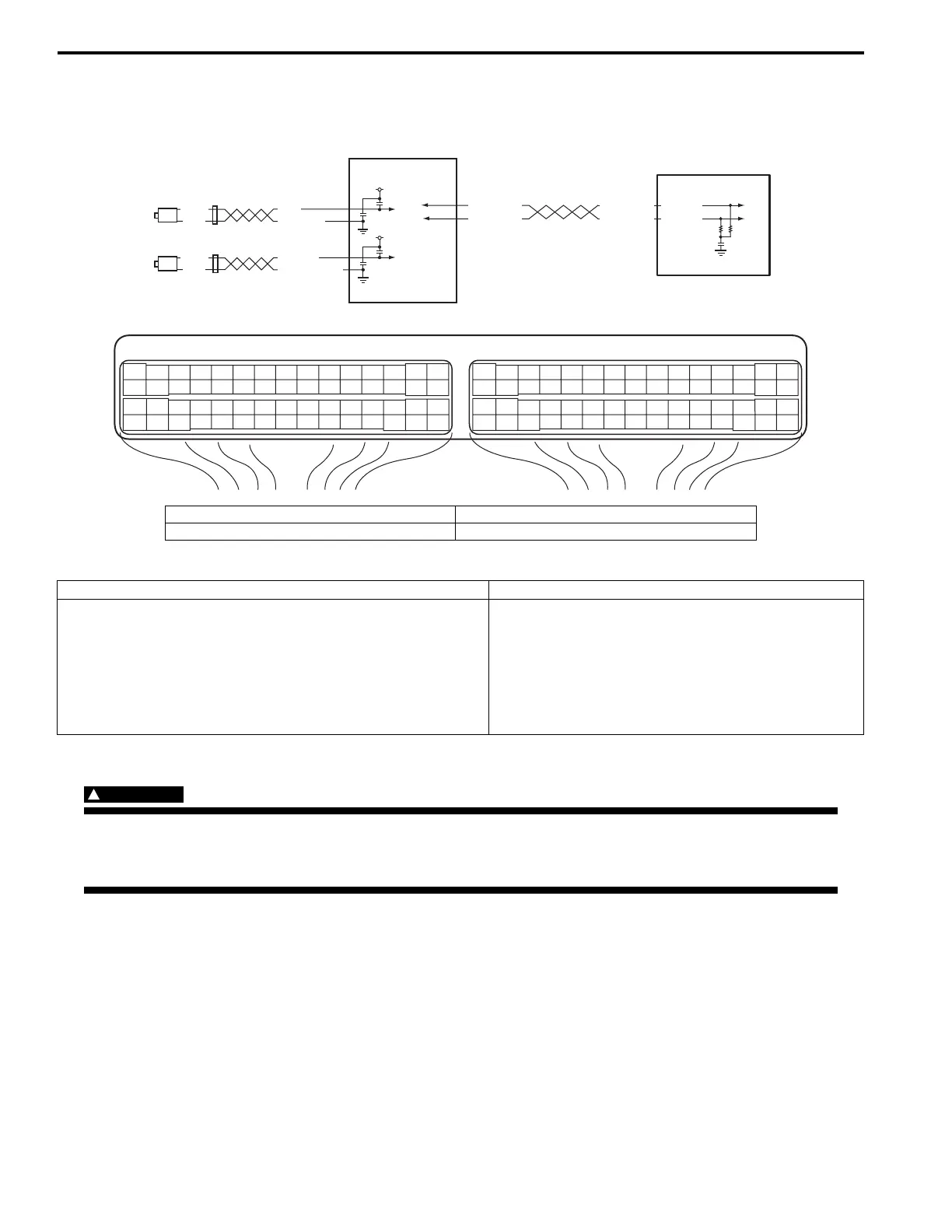
Wiring Diagram
DTC Detecting Condition and Trouble Area
DTC Confirmation Procedure
WARNING
!
• When performing a road test, select a place where there is no traffic or possibility of a traffic
accident and be very careful during testing to avoid occurrence of an accident.
• Road test should be carried out by 2 persons, a driver and a tester.
1) With ignition switch turned OFF, connect scan tool.
2) Turn ON ignition switch and clear DTC using scan tool.
3) Warm up engine to normal operating temperature.
4) Drive vehicle at 4000 rpm (engine speed) with 3rd gear (for M/T vehicle) or “3” range (for A/T vehicle).
5) Release accelerator pedal and with engine brake applied, keep vehicle coasting for 6 sec. or more (fuel cut
condition for 5 sec. or more) and stop vehicle.
6) For A/T model, drive vehicle at more than 3700 rpm for 10 sec.
7) Check pending DTC and DTC.
E23-4
E23-19
WHT/RED
WHT/BLU
WHT/RED
WHT/BLU
E23 C37
34
1819
5671011
1720
47 46495051
2122
52
1625
9
24
14
29
5557 54 53
59
60 58
2
262728
15
30
56 48
32 31343536374042 39 38
44
45 43 41 33
11213
23
834
1819
5671011
1720
47 46495051
2122
52
1625
9
24
14
29
5557 54 53
59
60 58
2
262728
15
30
56 48
32 31343536374042 39 38
44
45 43 41 33
11213
23
8
BLK
WHT
BLK
WHT
YEL/BLK
YEL
LT GRN
LT GRN/BLK
12V
12V
1
2
3
4
I5JB0A110060-03
1. Rear left side wheel speed sensor (VSS 1) 3. ABS / ESP® control module
2. Rear right side wheel speed sensor (VSS 2) 4. ECM
DTC detecting condition Trouble area
• Vehicle speed signal is not input while fuel is cut at
deceleration for 4 seconds continuously at 3600 rpm or
less.
• Vehicle speed signal is not input even if engine is running
with more than 3700 rpm at D-Range for 4 sec. (for A/T
model).
(2 driving cycle detection logic)
• Wheel speed sensor (VSS)
• Wheel speed sensor circuit
• ABS / ESP® control module
•ECM
 Loading...


