3C-53 Transfer: Motor-Shift Type (Transfer with Shift Actuator)
Inspection of 4WD Control Module and Its Circuits
S5JB0E3314030
4WD control module and its circuits can be checked at coupler connected to 4WD control module by measuring
voltage, pulse signal.
CAUTION
!
4WD control module cannot be checked by itself. It is strictly prohibited to connect voltmeter or
ohmmeter to 4WD control module with couplers disconnected from it.
Voltage and Signal Check
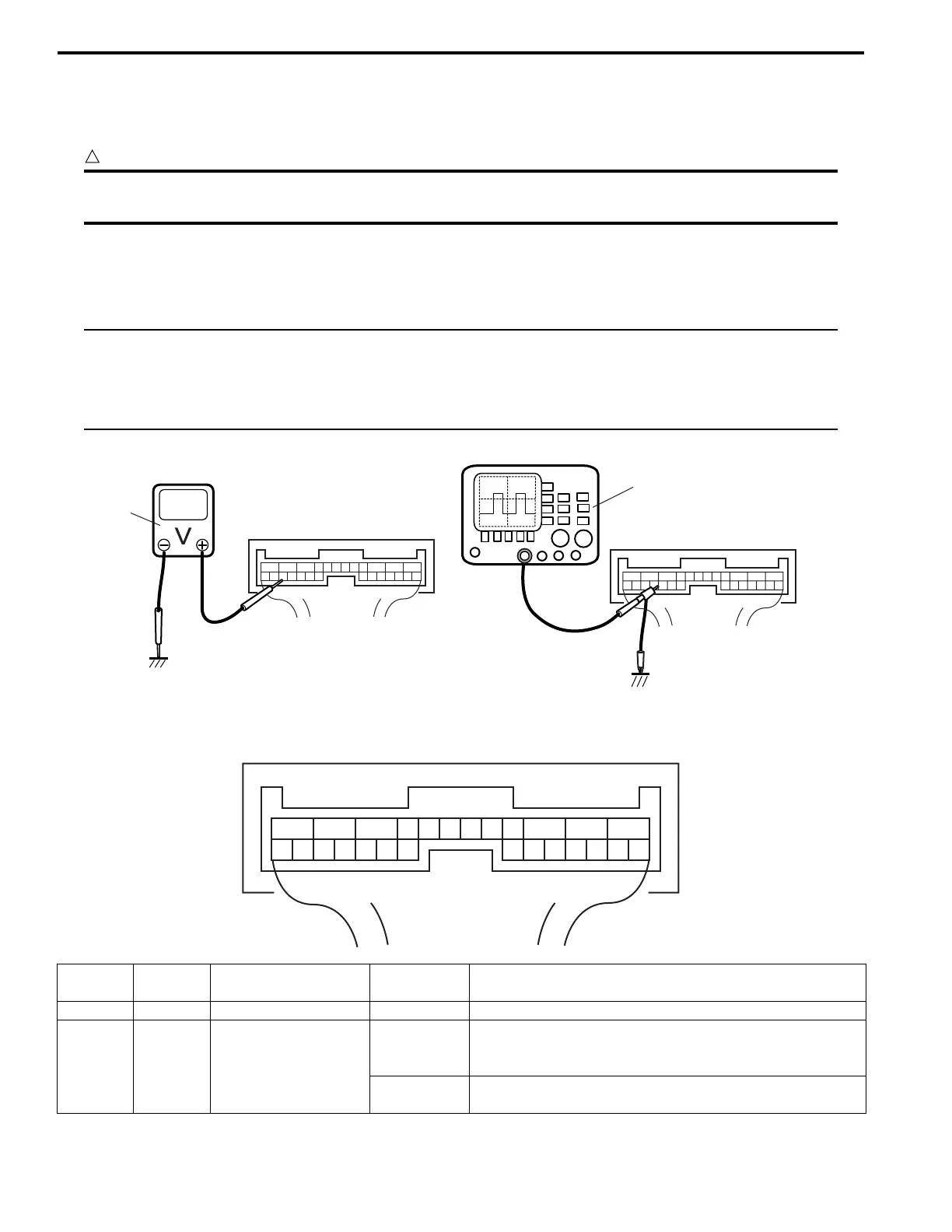
1) Check voltage using voltmeter (1) connected to each terminal of couplers.
2) Check signal using oscilloscope (2) connected to each terminal of couplers.
NOTE
• As each terminal voltage is affected by the battery voltage, confirm that it is 11 V or more when
ignition switch is turned ON.
• Pulse signal cannot be measured by voltmeter. It can be measured by oscilloscope.
• Item with asterisk (*) in normal voltage column can be read only by oscilloscope.
Terminal arrangement of 4WD control module connector (Viewed from harness side)
1
2
I4JA01332053-01
123456789101112
1314151617181920212223242526
I4JA01332054-01
Terminal
Number
Wire
Color
Circuit
Normal
Voltage
Condition
E91-1 BLK Ground 0 – 1 V —
E91-2 BLU
Transfer actuator
motor 1
10 – 14 V
Ignition switch turned to ON position and transfer shift
actuator being rotated N → 4H → 4H-lock direction or 4L-
lock → 4H-lock direction
0 – 1 V
Ignition switch turned to ON position and transfer shift
actuator in other than above-mentioned condition
 Loading...


