1A-62 Engine General Information and Diagnosis:
Reference waveform No.17
Mass air flow sensor signal (1) with engine racing
Reference waveform No.18
A/F sensor signal with engine idling
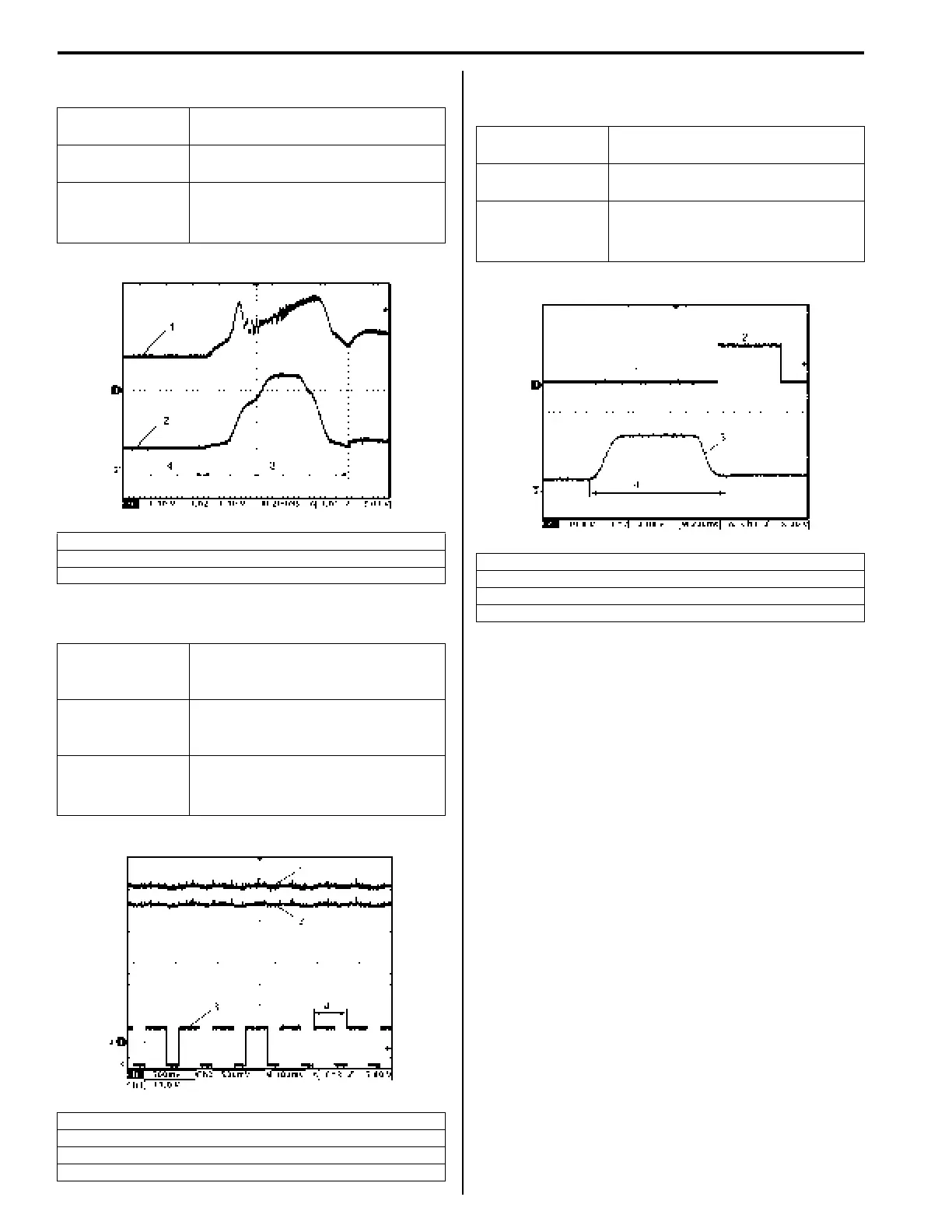
Reference waveform No.19
Intake manifold tuning vacuum solenoid valve signal with
engine racing (for J20 engine)
Measurement
terminal
CH1: “C37-26” to “C37-27”
CH2: “C37-54” to “C37-41”
Oscilloscope
setting
CH1: 1 V/DIV, CH2: 1 V/DIV
TIME: 200 ms/DIV
Measurement
condition
• After warmed up to normal
operating temperature
• Engine racing
2. Throttle position sensor (main) signal
3. Racing
4. Idle
Measurement
terminal
CH1: “C37-38” to “C37-58”
CH2: “C37-37” to “C37-58”
CH3: “C37-32” to “C37-31”
Oscilloscope
setting
CH1: 500 mV/DIV, CH2: 500 mV/
DIV, CH3: 10 V/DIV
TIME: 100 ms/DIV
Measurement
condition
• After warmed up to normal
operating temperature
• Engine at specified idle speed
1. A/F sensor signal (+)
2. A/F sensor signal (–)
3. A/F sensor heater signal
4. One duty cycle
I5JB0A110088-02
I5JB0A110089-01
Measurement
terminal
CH1: “C37-33” to “C37-58”
CH2: “C37-54” to “C37-41”
Oscilloscope
setting
CH1: 10 V/DIV, CH2: 2 V/DIV
TIME: 200 ms/DIV
Measurement
condition
• After warmed up to normal
operating temperature
• Engine racing
1. ON signal (IMT valve closed)
2. OFF signal (IMT valve opened)
3. Throttle position sensor (main) signal
4. Racing
I5JB0A110090-02
 Loading...


