ABS: 4E-36
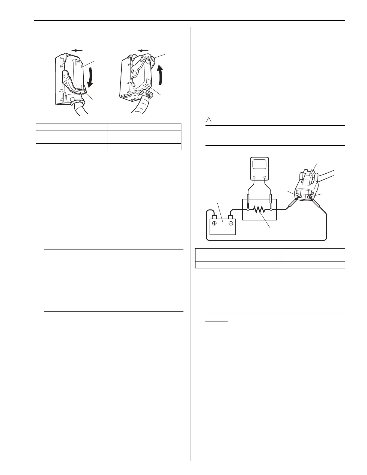
2) Connect ABS (ESP®) control module connector and
lock it as shown in figure.
3) Connect harness clamp to bracket.
4) Install ECM referring to “Engine Control Module
(ECM) Removal and Installation: in Section 1C in
related manual”.
5) Connect negative (–) cable at battery.
6) Bleed air from brake system referring to “Air
Bleeding of Brake System: in Section 4A in related
manual”.
7) Check each installed part for fluid leakage and
perform “Hydraulic Unit Operation Check: ”.
NOTE
For new ABS (ESP®) hydraulic unit / control
module assembly, if “Hydraulic Unit
Operation Check: ” has not been performed,
ABS warning lamp may flash when ignition
switch is turned ON position.
Accordingly preform “Hydraulic Unit
Operation Check: ” to stop flashing of ABS
warning lamp.
Front Wheel Speed Sensor On-Vehicle
Inspection
S5JB0E4506005
Output Voltage Inspection
1) Disconnect negative (–) cable from battery.
2) Hoist vehicle a little.
3) Disconnect wheel speed sensor connector.
4) Disconnect wheel speed grommet from vehicle body.
5) Set up measuring devices as shown in figure, the
resistance to 115 Ω and the power supply voltage to
12 V.
CAUTION
!
Incorrect voltage and/or wrong connection
cause damage to wheel speed sensor.
6) Measure voltage at resistance without wheel
rotation.
If voltage is out of specification, check sensor,
mating encoder and their installation conditions.
Voltage at the resistance (115
Ω) without wheel
rotation
680 to 960 mV
[A]: With ESP® 1. ESP® control module connector
[B]: Without ESP® 2. ABS control module connector
C: Pull down until lock to connect 3. Lock
D: Pull up until lock to connect
C
D
[A] [B]
1
3
3
2
I6JB01450018-03
1. Wheel speed sensor connector 4. “BLK” wire terminal
2. Resistance (115 Ω) 5. Power supply (12 V)
3. “WHT” wire terminal
V
4
1
3
2
5
I5JB0A450026-03
 Loading...


