Engine General Information and Diagnosis: 1A-31
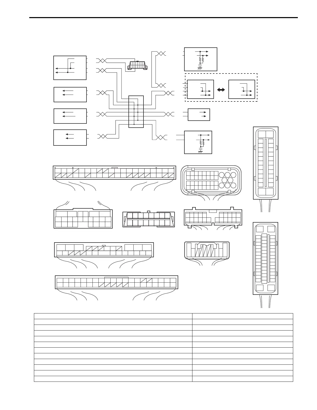
DTC P1674: CAN Communication (Bus Off Error)
S5JB0E1104064
Wiring Diagram
WHT
RED
WHT
RED
G44-18
G44-19
G44
[A] [B]
[C]
[H]
[G]
1234567891011141516
36 34 33 32 30 29 24 2337
181920
WHT/BLU
WHT/BLU
WHT/RED
WHT/RED
E23-4
E23-19
WHT
RED
WHT
RED
E92-17
E92-7
WHT
RED
E91-22
E91-23
WHT
RED
RED
G31-1
G31-3
G31-4
65
16 15 14 13 12 11
43
24 23 2122
10 9 8 7
21
1920 18 17
E92
E23
12345678910
1117 16151413122221201918
G28[F]
G31
E91
12347891011141516
36 3435 24 23 212228 27 25263739 3840
18 17 13 121920
123101112
161718 15 14 131920212526
56
[I]
E53
[E]
E03
15
16
17
18
19
20
21
22
23
24
25
2
3
4
5
6
7
8
9
10
11
12
1
13
14
26
G31-2
WHT
1
2
3
4
9
5
6
8
7
[K]
E03-12
E03-10
E03-6
E03-8
10
11
[L]
E53-13
E53-42
E53-44
E53-46
1718192021222324
25262728293031
3334353637383940
32
1
23
4
5
6
7
8
910111213141516
[D]
87654321
910111213141516
16
1
15
2
3
4
5
6
7
8
9
10
11
12
13
14
17
18
19
20
21
22
23
24
25
26
27
28
29
30
31
32
33
34
35
36
37
38
39
40
41
42
43
44
45
46
47
[J]
G45
109 321
WHT
RED
G45-9
G45-10
G28-8
G28-10
I5JB0D110007-01
[A]: Keyless start control module connector (if equipped) (viewed from harness side) 1. BCM
[B]: ECM connector (viewed from harness side) 2. 4WD control module (if equipped)
[C]: TCM connector (for A/T model) (viewed from harness side) 3. TCM (for A/T model)
[D]: DLC (viewed from terminal side) 4. Keyless start control module (if equipped)
[E]: ABS hydraulic unit / control module connector (viewed from terminal side) 5. DLC
[F]: Combination meter connector (viewed from harness side) 6. ECM
[G]: 4WD control module connector (viewed from harness side) 7. ABS hydraulic unit / control module assembly
[H]: BCM connector (viewed from harness side) 8. Combination meter
[I]: ESP® control module connector (viewed from harness side) 9. CAN circuit junction connector
[J]: Steering angle sensor connector (viewed from harness side) 10. ESP® control module
[K]: Vehicle without ESP® 11. Steering angle sensor (for vehicle with ESP®)
[L]: Vehicle with ESP®
 Loading...


