4E-5 ABS:
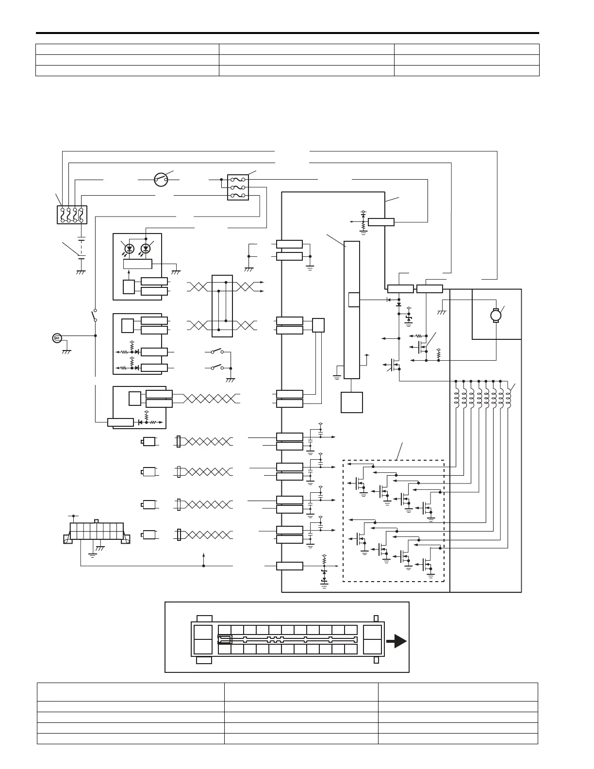
ABS Wiring Circuit Diagram
S5JB0E4502002
The figure shows for vehicle without ESP®. For vehicle equipped with ESP®, refer to “Electronic Stability Program
Wiring Circuit Diagram: in Section 4F”.
5. Solenoid valve driver (transistor) 14. Wheel speed sensor (Right-front) 23. Yaw rate / G sensor assembly
6. Pump motor driver (transistor) 15. Wheel speed sensor (Left-front)
7. Solenoid valve 16. Wheel speed sensor (Right-rear)
[A]
14
1516171819202122232425
1
23456789101112
13
26
E03
a
12V
12V
27
WHT/RED
WHT/GRN
BLK/YEL
WHT/RED
M
12V
GRN/ORN
1
2
3
4
8
10
11
12
13
12V
5V
12V
23
24
VCC
22
WHT/BLU
WHT/BLU
14
15
16
17
PPL/WHT
18
19
+BB
PPL/RED
WHT
BLK
WHT
BLK
WHT
BLU/BLK
GRN/BLK
BLU
GRN
YEL/BLK
YEL
LT GRN
LT GRN/BLK
E03-21
E03-22
E03-19
E03-18
E03-15
E03-16
E03-25
E03-24
E03-7
E03-13
E03-26
BLK
BLK
E03-5
E03-14 E03-1
RED/BLK
RED/BLK
E03-12
E03-6
RED
WHT
RED
WHT
WHT/RED
WHT/BLU
E03-10
E03-8
RED
WHT
12V
12V
12V
12V
12V
BLK
WHT
BLK
WHT
20
29
28
7
6
5
30
31
25
9
32
32
32
G31-1
G31-3
G31-1
G31-3
G31-7
G31-8
26
32
E23-4
E23-19
GRN/WHT
21
GRN
12V
E23-20
I5JB0D450003-02
[A]: Terminal arrangement of ABS hydraulic unit / control
module assembly
11. Pump motor driver (transistor) 23. Internal memory
a: Upside 12. Pump motor 24. Solenoid valve driver (transistor)
1. Battery 13. Solenoid valves 25. G sensor (4WD vehicle only)
2. Main fuse box 14. Right-rear wheel speed sensor 26. ECM
3. Ignition switch 15. Left-rear wheel speed sensor 27. BCM
 Loading...


