3C-35 Transfer: Motor-Shift Type (Transfer with Shift Actuator)
DTC C1227: 4L/N Switch Circuit Open
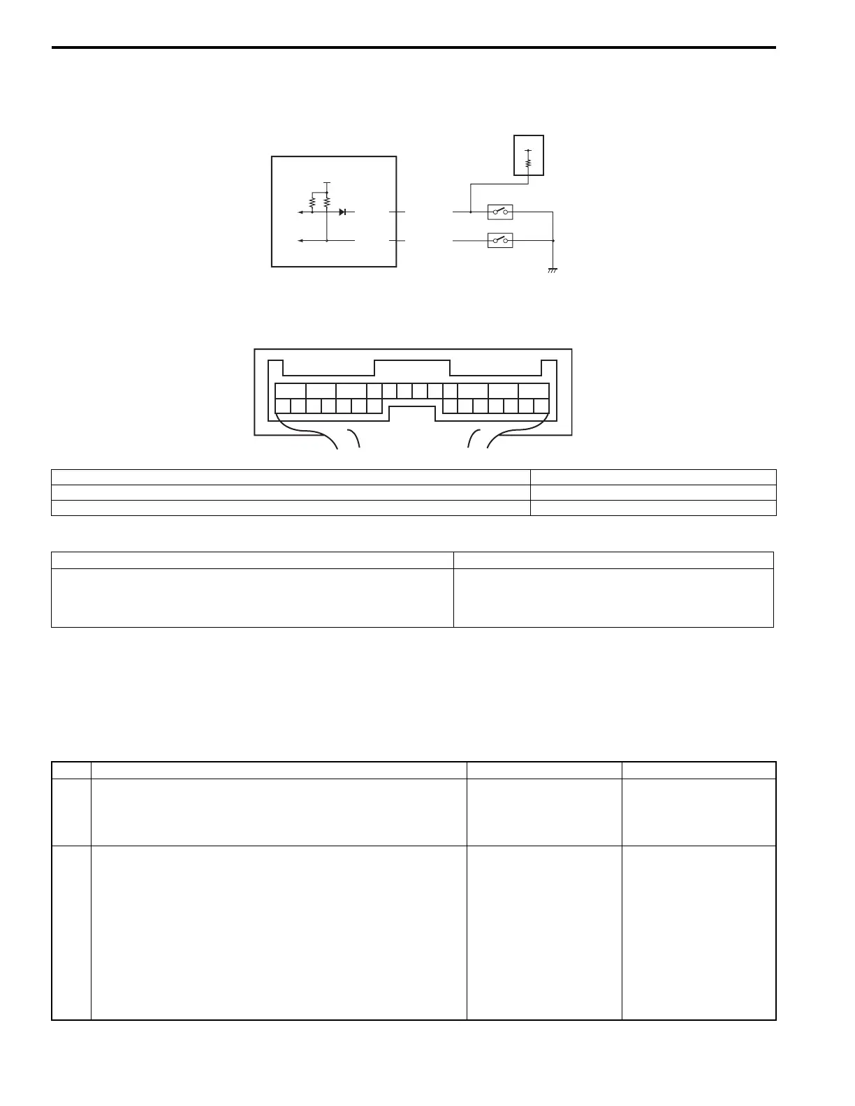
S5JB0E3314018
Wiring Diagram
DTC Detecting Condition and Trouble Area
DTC Confirmation Procedure
1) Clear DTC using scan tool.
2) Select transfer switch to “4L-lock” position and keep its position for 1 min.
3) Check DTC.
Troubleshooting
IG
E91-13
E91-14
RED/GRN
PNK/WHT
2
3
4
12V
1
1
2
3
45
6
7
891011
12
13
14
1516
1718
19
20
21
22
23
24
25
26
[A]
I5JB0A332018-01
[A]: 4WD control module connector “E91” (viewed from harness side) 3. 4L/N switch
1. 4WD control module 4. Center differential lock switch
2. TCM
DTC detecting condition Trouble area
Though transfer shift actuator motor position switch is “4L-lock”
position, the ON signal is not input from the 4L/N switch.
• 4L/N switch
• 4L/N switch circuit
• 4WD control module
Step Action Yes No
1 Was “4WD control system check” performed? Go to Step 2. Go to “4WD Control
System Check: Motor-
Shift Type (Transfer with
Shift Actuator)”.
2 4L/N switch circuit check
1) Disconnect 4L/N switch connector with ignition switch
OFF.
2) Check for proper connection to terminal of 4L/N switch
connector.
3) If connection is OK, measure voltage between “PNK/
WHT” terminal of 4L/N switch connector and vehicle
body ground with ignition switch ON.
Is it 10 – 14 V?
Go to Step 3. Go to Step 4.
 Loading...


