9B-1 Lighting Systems:
Lighting Systems
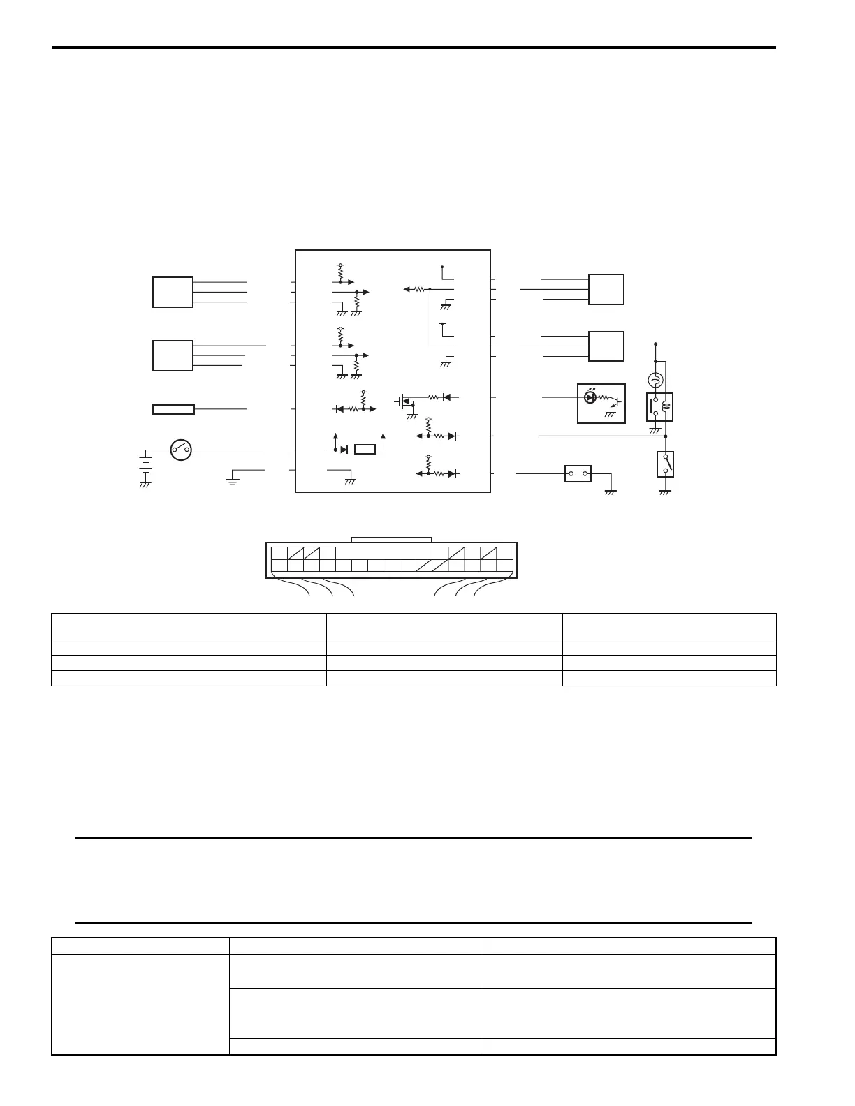
Schematic and Routing Diagram
Headlight Auto Leveling System wiring Circuit Diagram
S5JB0E9202001
Diagnostic Information and Procedures
DRL System Symptom Diagnosis (If Equipped)
S5JB0E9204006
NOTE
• Use of SUZUKI scan tool makes it easy to check whether a faulty condition is on the input side or
output side of BCM. For checking procedure, refer to “Diagnosis Using Output Test Function of
SUZUKI Scan Tool” under “Scan Tool Data: in Section 10B”.
• Check each part in the order from the top of the following list.
G51-12
G51-19
G51-21
G51-10
G51-23
+B
5V
5V
YEL/RED
GRN/RED
BLK
G51-1
12V
GRN
GRN/YEL
GRN/WHT
YEL
3
G51-13
G51-20
G51-22
5V
BLU/RED
BLU/YEL
BLU/BLK
2
4
5
9
10
11
1
5V
5V
12V
G51-16
G51-3
BLU/BLK
RED/BLU
5V
G51-5
PNK
G51-17
RED
G51-11
G51-24
YEL/GRN
GRN/BLK
6
12V
G51-18
GRN
7
8
G51-6
G51-9
BLU/WHT
G51
101112131617181920
31569
21222324
[A]
I5JB0D920001-01
[A]: Headlight leveling control module connector (viewed
from harness side)
4.
BCM
8.
Headlight leveling warning light
1. Headlight leveling control module 5. Right headlight leveling actuator 9. Ignition switch
2. Front height sensor 6. Left headlight leveling actuator 10. Lighting switch
3. Rear height sensor 7. Combination meter 11. Diagnosis connector
Condition Possible cause Correction / Reference Item
Headlight does not light
when lighting switch is in
OFF position and engine
is running
Lighting switch faulty Check lighting switch referring to “Headlight
Switch (in Lighting Switch) Inspection: ”.
BCM faulty Check BCM for function referring to “Inspection
of BCM and its Circuits: in Section 10B in
related manual”.
Wiring or grounding faulty Repair circuit.
 Loading...


