5A-7 Automatic Transmission/Transaxle:
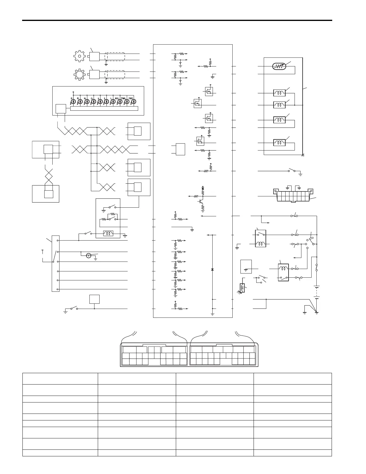
Electronic Shift Control System Wiring Diagram
13
34
34
34
34
11
12
35
P
R
N
D
2
L
14
5V
12V
12V
12V
12V
BLK
BLK/ORN
BLK/ORN
IG11
BLK/RED
BLK/WHT
+BB
WHT
16
21
17
18
20
12V
19
23
30
25
24
26
27
28
29
WHT
WHT
RED
WHT
RED
RED
65
16 15 14 13 12 11
43
24 23 2122
10 9 8 7
21
1920 18 17
E92
17 16
26 25
15 14
65 342
13 12
23 2224
11 10 9
21 20 19
87
18
1
E93
[A]
32
33
RED
BLU
WHT
P
N
GRN
YEL/BLK
ORN
GRN/RED
YEL/RED
BRN/RED
GRN/YEL
PPL/WHT
E92-11
E92-12
E92-16
E92-15
E92-4
E92-2
E92-1
E92-23
E92-6
E92-24
E92-5
E92-3
RED
YEL/GRN
PNK/BLU
PNK/GRN
PNK/BLK
PNK/WHT
YEL/BLK
YEL/RED
GRN/ORN
GRN/WHT
E92-20
E92-10
E93-4
E93-12
E93-23
E93-20
E93-1
E93-8
E93-7
E93-19
E93-18
E92-17
E92-7
5
IG11
12V
31
PPL/WHT
34
WHT
RED
34
WHT
RED
34
WHT
RED
WHT
RED
2.5V
WHT
ORN
1
2
E93-5
E93-14
2.5V
BLU
PNK
E93-6
E93-16
15
6
9
BLK/WHT
3
6
4
5
7
8
10
22
I5JB0A510009-03
[A]: TCM connector (viewed from
harness side)
9. P/N mode switch 18. Shift solenoid valve-B 27. “IG COIL” fuse
1. Output shaft speed sensor 10. “3” position switch 19. TCC pressure control solenoid
valve
28. “ST SIG” fuse
2. Input shaft speed sensor 11. Shift lock solenoid 20. Pressure control solenoid valve 29. “ST” fuse
3. Combination meter 12. Brake light switch 21. Valve body assembly 30. AT relay included in integration
relay No.2 in main fuse box
4. ABS/ESP® control module 13. Transmission range switch 22. Monitor connector (if equipped) 31. Starting motor relay
5. ECM 14. Back-up light 23. DLC 32. Inhibit switch
6. 4WD control module (if
equipped)
15. 4L/N switch (if equipped) 24. Ignition switch 33. Starting motor
7. Keyless start control module
(if equipped)
16. Transmission fluid temperature
sensor
25. “DOME” fuse 34. CAN driver
8. BCM 17. Shift solenoid valve-A 26. “AT” fuse 35. Meter driver
 Loading...


