1A-12 Engine General Information and Diagnosis:
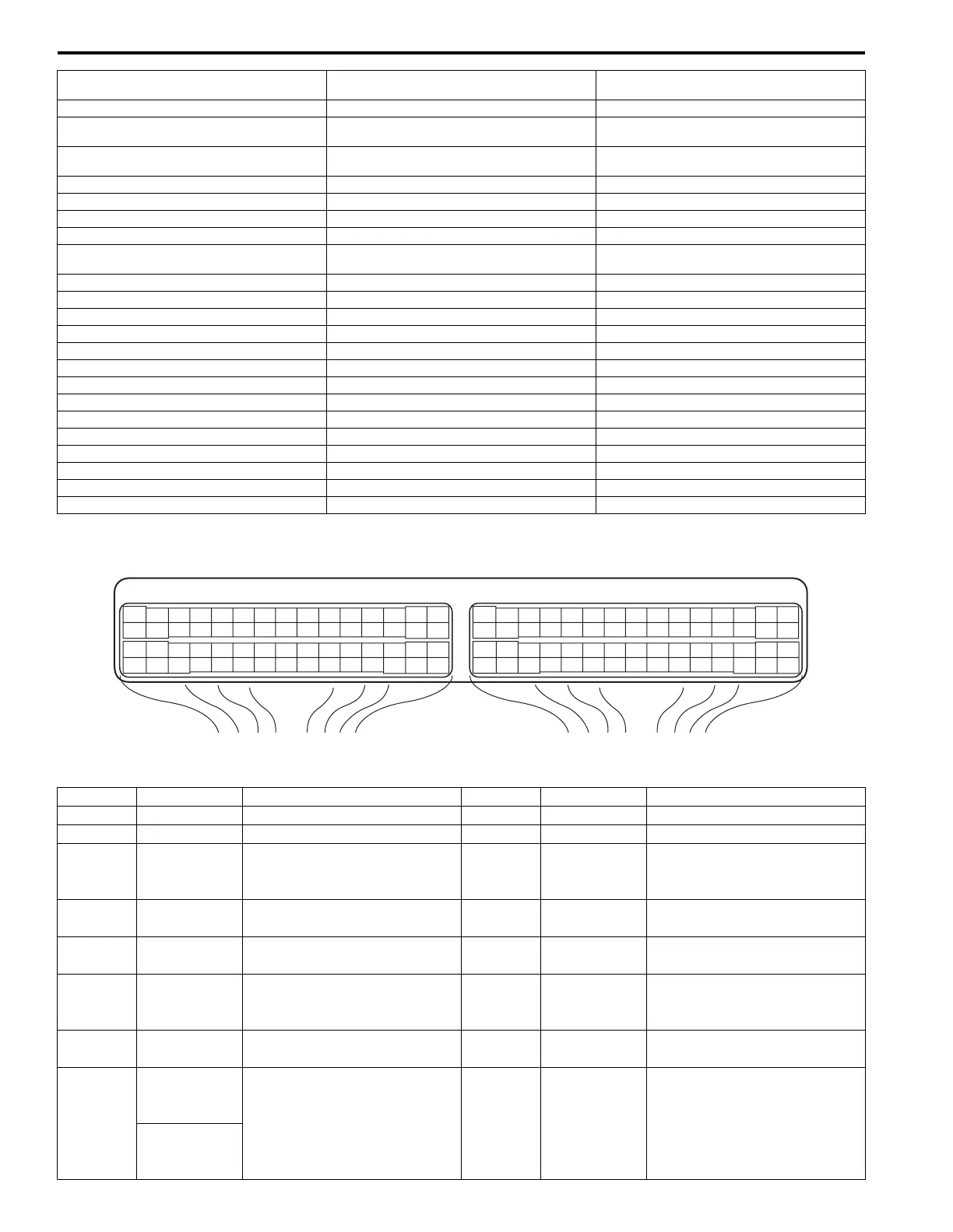
Terminal Arrangement of ECM Coupler (Viewed from Harness Side)
Connector: C37
1. Accelerator pedal position (APP) sensor
assembly
24. DLC 47. A/C compressor (if equipped with A/C)
2. Shield wire 25. To BCM and ABS / ESP® control module 48. “CPRSR” fuse
3. CMP sensor 26. Barometric pressure sensor 49. Ignition coil assembly (for No.1 and No.4
spark plugs)
4. CKP sensor 27. Throttle actuator control relay 50. Ignition coil assembly (for No.2 and No.3
spark plugs)
5. MAF and IAT sensor 28. “THR MOT” fuse 51. “IG COIL” fuse
6. CO adjust resistor (if equipped) 29. Electric throttle body assembly 52. Main relay
7. MAP sensor 30. Throttle actuator 53. “IG2 SIG” fuse
8. ECT sensor 31. Throttle position sensor 54. “DOME” fuse
9. A/C refrigerant pressure sensor (if equipped
with A/C)
32. Fuel injector No.1 55. “FI” fuse
10. Generator 33. Fuel injector No.2 56. Ignition switch
11. “O2 HTR” fuse 34. Fuel injector No.3 57. “IGN” fuse
12. HO2S heater relay 35. Fuel injector No.4 58. “STR MOT” fuse
13. HO2S-2 36. EVAP canister purge valve 59. “ST SIG” fuse
14. A/F sensor 37. EGR valve 60. Starting motor control relay
15. Knock sensor 38. Oil control valve (Camshaft position control) 61. Starting motor
16. Power steering pump pressure switch 39. Fuel pump relay 62. Diagnosis connector (if equipped)
17. Immobilizer coil antenna (if equipped) 40. Fuel pump 63. Battery
18. ABS / ESP® control module 41. Radiator cooling fan relay No.1 64. Engine ground
19. BCM 42. Radiator cooling fan relay No.2 65. Body ground
20. Combination meter 43. Radiator cooling fan relay No.3 66. Main fuel level sensor
21. Steering angle sensor (for vehicle with ESP®) 44. Radiator cooling fan motor No.1 67. Sub fuel level sensor
22. Stop lamp switch 45. Radiator cooling fan motor No.2
23. Stop lamp 46. A/C compressor relay (if equipped with A/C)
E23 C37
34
1819
5671011
1720
47 46495051
2122
52
1625
9
24
14
29
5557 54 53
59
60 58
2
262728
15
30
56 48
32 31343536374042 39 38
44
45 43 41 33
11213
23
834
1819
5671011
1720
47 46495051
2122
52
1625
9
24
14
29
5557 54 53
59
60 58
2
262728
15
30
56 48
32 31343536374042 39 38
44
45 43 41 33
11213
23
8
I4RS0A110008-01
Terminal Wire color Circuit Terminal Wire color Circuit
1 PNK Fuel injector No.1 31 BLK/YEL Ground for A/F sensor heater
2 PNK/BLK Fuel injector No.2 32 PNK/BLU Heater output of A/F sensor
3YEL/GRN
EGR valve (stepper motor coil
3)
33 GRY/RED
Intake manifold tuning vacuum
solenoid valve output
(for J20 engine)
4 YEL
EGR valve (stepper motor coil
4)
34 RED/BLU
Ground for A/F sensor
adjusting resistor
5 YEL/BLK
EGR valve (stepper motor coil
1)
35 RED/YEL
A/F sensor adjusting resistor
signal
6 YEL/RED
EGR valve (stepper motor coil
2)
36 PNK
Crankshaft position (CKP)
sensor (–)
(for J20 engine)
7BLU/ORN
Power steering pump pressure
switch signal
37 BLK A/F sensor signal (–)
8
BRN/RED
(for M16
engine) Generator field coil monitor
signal
38 WHT A/F sensor signal (+)
BRN/BLK
(for J20
engine)
 Loading...


