Engine General Information and Diagnosis: 1A-71
Electric Load Signal Circuit Check
S5JB0E1104086
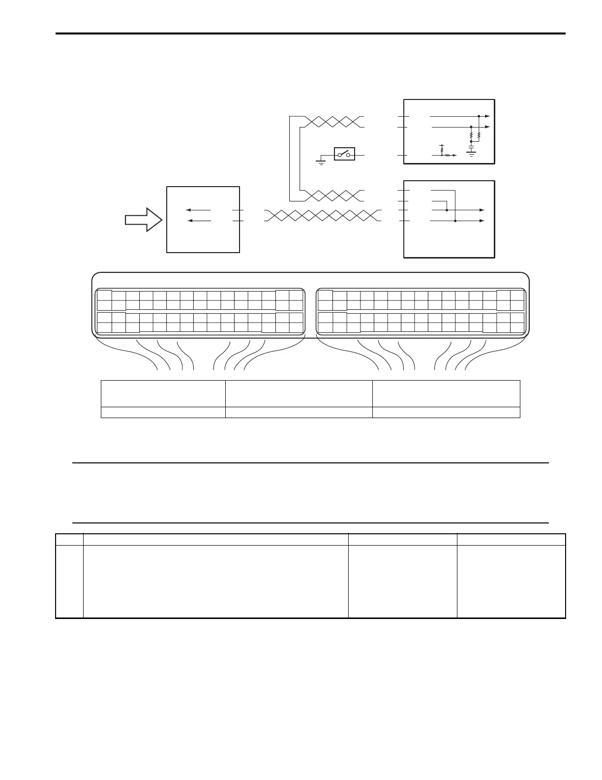
Wiring Diagram
Troubleshooting
NOTE
• Before performed troubleshooting, be sure to read the “Precautions of ECM Circuit Inspection: in
related manual”.
• When measuring circuit voltage, resistance and/or pulse signal at ECM connector, connect the
special tool to ECM and/or the ECM connectors referring to “Inspection of ECM and Its Circuits: ”.
WHT/BLU
BLU/ORN
WHT/RED
E23 C37
34
1819
5671011
1720
47 46495051
2122
52
1625
9
24
14
29
5557 54 53
59
60 58
2
262728
15
30
56 48
32 31343536374042 39 38
44
45 43 41 33
11213
23
834
1819
5671011
1720
47 46495051
2122
52
1625
9
24
14
29
5557 54 53
59
60 58
2
262728
15
30
56 48
32 31343536374042 39 38
44
45 43 41 33
11213
23
8
E23-4
E23-19
1
RED
WHT
E03-12
E03-6
WHT/BLU
WHT/RED
E03-8
E03-10
RED
WHT
G31-3
G31-1
2
C37-7
3
5
12V
4
I5JB0A110104-02
1. ECM 3. ABS / ESP® control module 5. Electric load signal (blower motor
signal, rear defogger signal, headlight
signal and A/C switch signal), etc.
2. BCM 4. PSP switch
Step Action Yes No
1 DTC check
1) Connect scan tool to DLC with ignition switch turned
OFF.
2) Turn ON ignition switch and check DTC.
Is there DTC P1674 and/or P1678?
Go to applicable DTC
diag. flow.
Go to Step 2.
 Loading...


