Engine General Information and Diagnosis: 1A-67
Resistance Check
1) Remove ECM from its bracket referring to “Engine Control Module (ECM) Removal and Installation: in Section 1C
in related manual”.
CAUTION
!
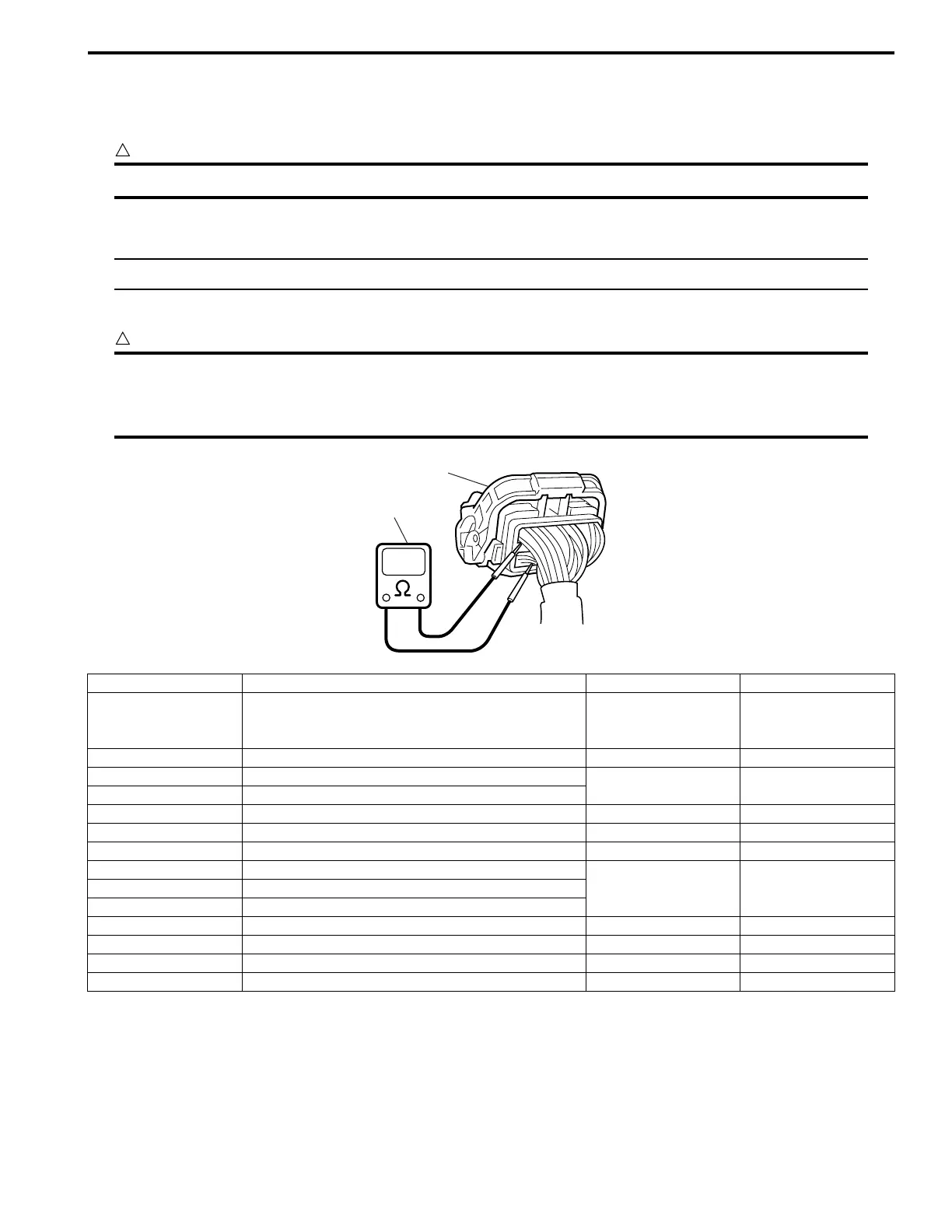
Never touch terminals of ECM itself or connect voltmeter or ohmmeter (2).
2) Connect special tool to ECM connectors securely.
NOTE
Do not connect the other connector of special tool to ECM.
3) Check resistance between each pair of terminals of disconnected connectors (1) as listed in the following table.
CAUTION
!
• Be sure to connect ohmmeter probe from wire harness side of coupler.
• Be sure to turn OFF ignition switch for this check.
• Resistance in the following table represents that measured when parts temperature is 20 °C (68 °F).
1
2
I4RS0A110086-02
Terminals Circuit Standard resistance Condition
E23-60 to E23-29 Main relay 160 – 240 Ω
Battery disconnected
and ignition switch
turned ON
E23-15 to E23-29 Fuel pump relay 160 – 240 Ω —
C37-16 to E23-1/16 No.3 fuel injector
10.8 – 18.2 Ω —
C37-17 to E23-1/16 No.4 fuel injector
C37-5 to E23-1/16 EGR valve (stepping motor No.1 coil) 20 – 31 Ω —
C37-13 to E23-1/16 EVAP canister purge valve 28 – 35 Ω —
C37-2 to E23-1/16 No.2 fuel injector 10.8 – 18.2 Ω —
C37-6 to E23-1/16 EGR valve (stepping motor No.2 coil)
20 – 31 Ω —C37-3 to E23-1/16 EGR valve (stepping motor No.4 coil)
C37-4 to E23-1/16 EGR valve (stepping motor No.3 coil)
C37-1 to E23-1/16 No.1 fuel injector 10.8 – 18.2 Ω —
C37-33 to E23-1/16 Intake manifold tuning vacuum solenoid valve 33 – 45 Ω —
C37-60 to C37-59 Oil control valve (for M16 engine) 6 – 15 Ω —
E23-50 to E23-1/16 Throttle actuator control relay 160 – 240 Ω —
 Loading...


