Electronic Stability Program: 4F-36
DTC C1057: ESP® (ABS) control module power supply circuit failure
S5JB0E4604016
Refer to “DTC C1057: ABS (ESP®) Control Module Power Supply Circuit Failure: in Section 4E”.
DTC C1061: Pump Motor and/or Motor Driver Circuit Failure
S5JB0E4604017
Refer to “DTC C1061: Pump Motor and/or Motor Driver Circuit: in Section 4E”.
DTC C1063: Solenoid Valve Power Supply Driver Circuit Failure
S5JB0E4604018
Refer to “DTC C1063: Solenoid Valve Power Supply Driver Circuit Failure: in Section 4E”.
DTC C1071: ESP® (ABS) Control Module Internal Defect
S5JB0E4604019
Refer to “DTC C1071: ABS (ESP®) Control Module Internal Defect: in Section 4E”.
DTC C1073: Lost Communication With Yaw Rate / G Sensor Assembly
S5JB0E4604038
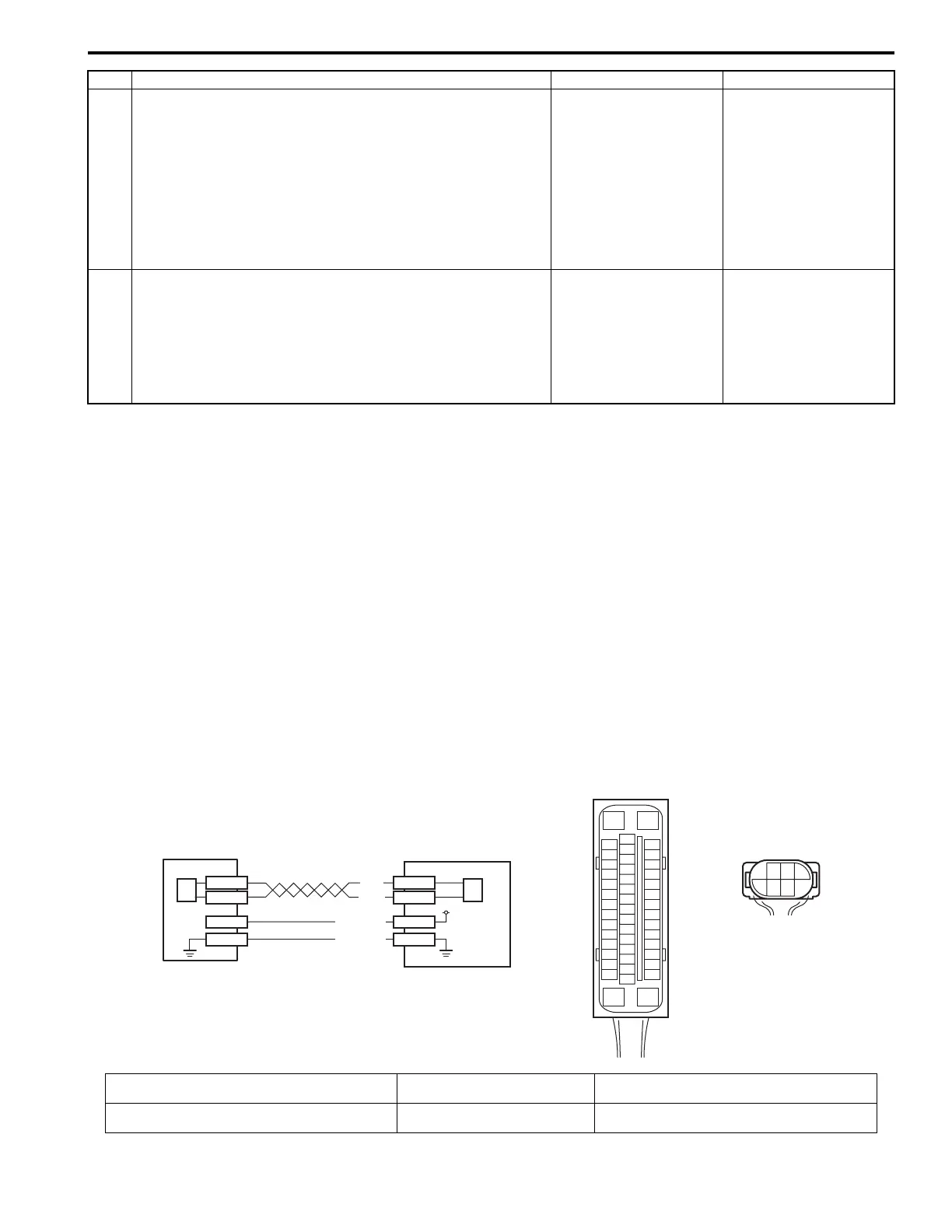
Wiring Diagram
3 Check back up light switch circuit
1) Turn ignition switch to OFF position.
2) Disconnect ESP® control module connector.
3) Check for proper connection to ESP® control module
connector terminal at “E53-10”.
4) If OK, then measure voltage between connector terminal
“E53-10” and vehicle body ground.
Is it 0 V?
Go to Step 4. “RED” wire circuit is
shorted to power circuit.
4 Check back up light switch circuit
1) Turn ignition switch to ON position.
2) Measure voltage between connector terminal “E53-10”
and vehicle body ground with the shift lever in “Reverse”
position.
Is it 10 – 14 V?
Substitute a known-
good ESP® hydraulic
unit / control module
assembly and recheck.
“RED” wire circuit open.
Step Action Yes No
[A]
E53
16
1
15
2
3
4
5
6
7
8
9
10
11
12
13
14
17
18
19
20
21
22
23
24
25
26
27
28
29
30
31
32
33
34
35
36
37
38
39
40
41
42
43
44
45
46
47
E53-29
E53-25
E53-37
E53-31
L39-3
L39-5
BLK
WHT
L39-2
L39-1
12V
PNK/GRN
PNK/WHT
[B]
L39
3
5
21
46
1
2
3
2
I6JB01460022-03
[A]: ESP® control module connector (viewed from
terminal side)
1. Yaw rate / G sensor assembly 3. ESP® hydraulic unit control module assembly
[B]: Yaw rate / G sensor assembly connector (viewed
from harness side)
2. CAN driver (for yaw rate / G
sensor assembly)
 Loading...


