How to ? Trigger on a pattern
The instrument determines the trigger point in the following manner:
It waits for the logic condition to become True.
It starts timing and waits for the logic function to become False.
It compares the times and, if the time True is longer (More Than Time) or shorter (Less Than
Time), then it triggers a waveform display at the point the logic condition became False. This
time can be, and usually is, different from the time set.
9. You can set the mode and holdoff for all standard trigger types. Refer to trigger mode
(see page 389)
and set holdoff (see page 474) to learn more about trigger mode and holdoff.
Pattern triggers
A pattern trigger occurs when the inputs to the selected logic function cause the function to become
True or False. When you use a pattern trigger, you define:
The precondition for each logic input: logic high, low, or "don't care"; the logic inputs are the
instrument channels
The Boolean logic function: AND, NAND, OR, or NOR
The condition for triggering: the Boolean function becomes True (logic high) or False (logic
low), and whether the True condition is time qualified
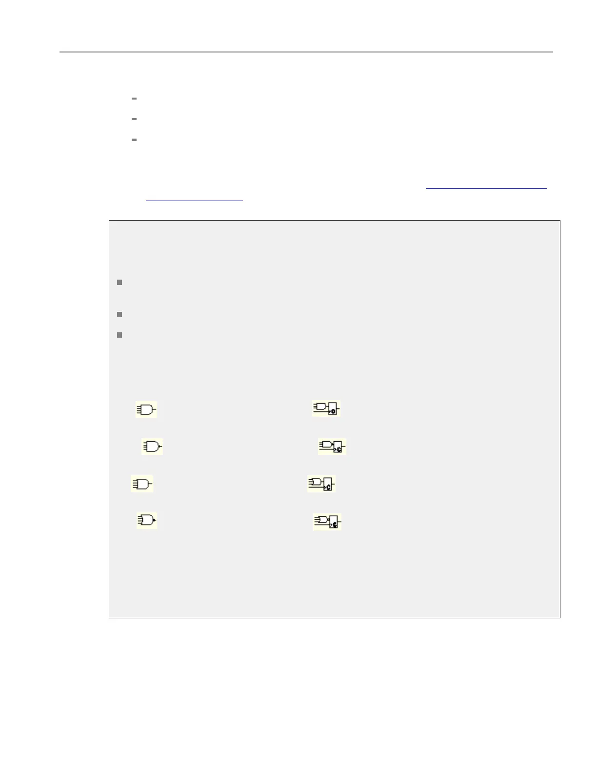
Pattern trigger logic choices are summarized in the following table.
Pattern State Definition
1
,
2
AND
Clocked AND
If all the preconditions selected for
the logic inputs
3
are TRUE, then the
instrument triggers.
NAND
Clocked NAND
If not all of the preconditions
selected for the logic inputs
3
are
TRUE, then the instrument triggers.
OR
Clocked OR
If any of the preconditions selected
for the logic inputs
3
are TRUE, then
the instrument triggers.
NOR
Clocked NOR
If none of the preconditions selected
for the logic inputs
3
are TRUE, then
the instrument triggers.
xxx
1
For state triggers, the definition must be met at the time the clock input changes state
2
The definitions given here are correct for the Goes TRUE setting in the Trigger When menu. If that menu is set to Goes False, swap the
definition for AND with that for NAND and for OR with NOR for both pattern and state types.
3
The logic inputs are channels 1, 2, 3, and 4 when using Pattern triggers. For State triggers, channel 4 becomes the clock input, leaving
the remaining channels as logic inputs.
DSA/DPO70000D, MSO/DPO/DSA70000C, DPO7000C, and MSO/DPO5000 Series 649
 Loading...


