xStack® DGS-3120 Series Layer 3 Managed Gigabit Ethernet Switch Web UI Reference Guide
165
a number between 1 and 65535.
Backup State
Each IP address can only have one primary route, while other routes should be assigned
to the backup state. When the primary route failed, switch will try the backup routes
according to the order learnt by the routing table until route success. The field represents
the Backup state that the Static and Default Route is configured for.
NULL Interface
Specify to enable or disable the NULL function for the routes. The null interface provides
an alternative method of filtering traffic. Packets send to null interface will be dropped by
the switch. (RI Mode Only)
Click the Apply button to accept the changes made.
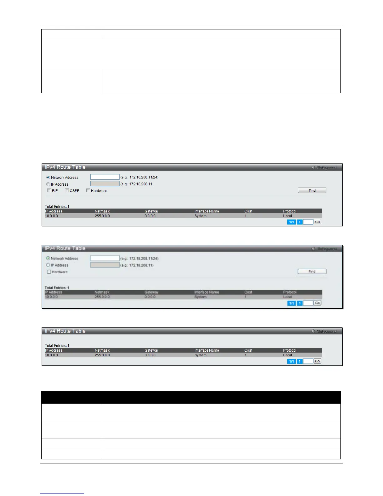
IPv4 Route Table
The IP routing table stores all the external routes information of the Switch. This window is used to display all the
external route information on the switch.
To view the following window, click L3 Features > IPv4 Route Table, as shown below:
Figure 5-4 IPv4 Route Table window (RI Mode Only)
Figure 5-5 IPv4 Route Table window (EI Mode Only)
Figure 5-6 IPv4 Route Table window (SI Mode Only)
The fields that can be configured are described below:
Parameter Description
Network Address
Click the radio button and enter the destination network address of the route to be
displayed. (RI and EI Mode Only)
IP Address
Click the radio button and enter the destination IP address of the route to be displayed.
The longest prefix matched route will be displayed. (RI and EI Mode Only)
Specifies to display routes that are related to RIP. (RI Mode Only)
Specifies to display routes that are related to OSPF. (RI Mode Only)
 Loading...