xStack® DGS-3120 Series Layer 3 Managed Gigabit Ethernet Switch Web UI Reference Guide
29
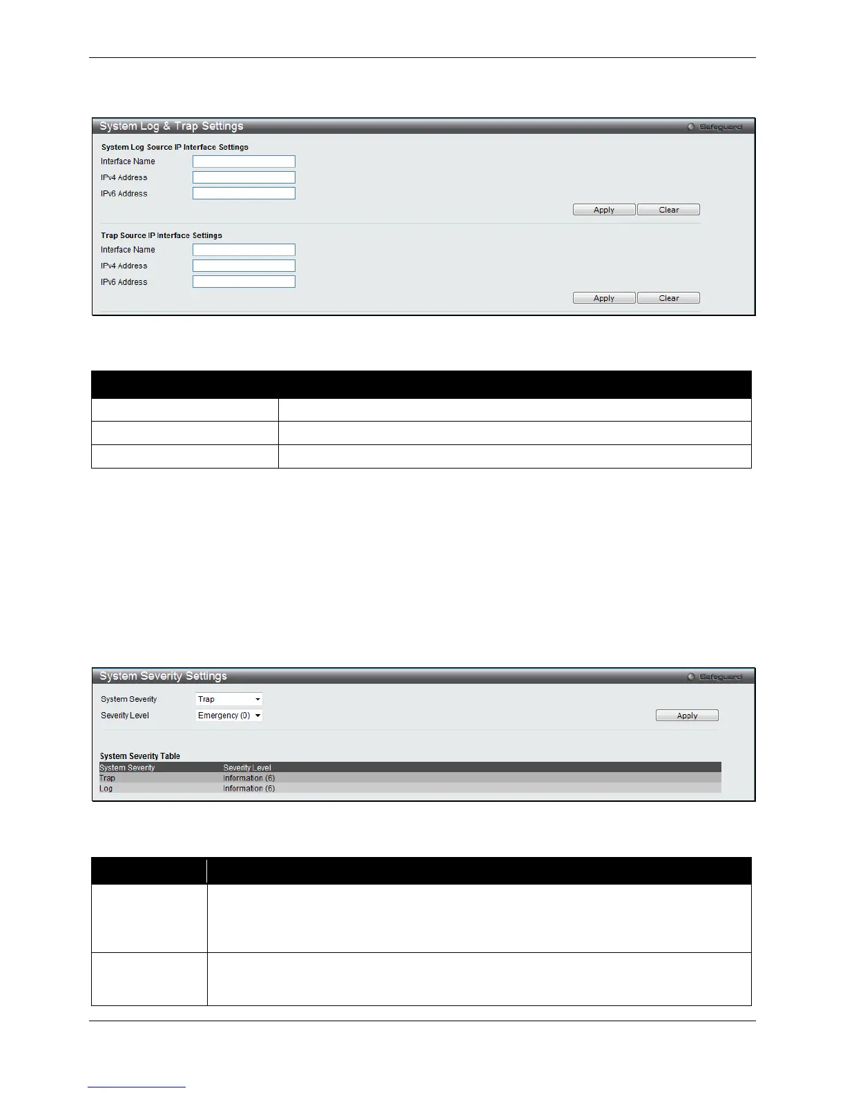
To view the following window, click System Configuration > System Log Configuration > System Log & Trap
Settings, as shown below:
Figure 2-27 System Log & Trap Settings window
The fields that can be configured are described below:
Parameter Description
Enter the IP interface name used.
Enter the IPv4 address used.
Enter the IPv6 address used.
Click the Apply button to accept the changes made for each individual section.
Click the Clear button to clear all the information entered in the fields.
System Severity Settings
The Switch can be configured to allow alerts be logged or sent as a trap to an SNMP agent. The level at which the
alert triggers either a log entry or a trap message can be set as well. Use the System Severity Settings window to
set the criteria for alerts. The current settings are displayed below the System Severity Table.
To view the following window, click System Configuration > System Log Configuration > System Severity
Settings, as shown below:
Figure 2-28 System Severity Settings window
The fields that can be configured are described below:
Parameter Description
System Severity Choose how the alerts are used from the drop-down menu. Select Log to send the alert of
the Severity Type configured to the Switch’s log for analysis. Choose Trap to send it to an
SNMP agent for analysis, or select All to send the chosen alert type to an SNMP agent and
the Switch’s log for analysis.
Severity Level
This drop-down menu allows you to select the level of messages that will be sent. The
options are Emergency (0), Alert (1), Critical (2), Error (3), Warning (4), Notice (5),
Information (6) and Debug (7).
 Loading...