xStack® DGS-3120 Series Layer 3 Managed Gigabit Ethernet Switch Web UI Reference Guide
201
Click the Delete button to remove the selected entry.
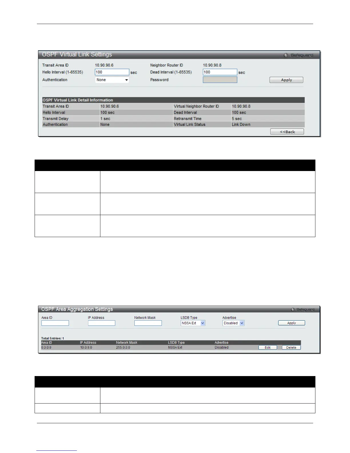
After clicking the Edit button, the following page with be displayed.
Figure 5-50 OSPF Virtual Link Settings – Edit window
The fields that can be configured are described below:
Parameter Description
Hello Interval (1-65535)
Allows the specification of the interval between the transmissions of OSPF Hello
packets, in seconds. The Hello Interval, Dead Interval, Authorization Type, and
Authorization Key should be the same for all routers on the same network.
Dead Interval (1-65535)
Allows the specification of the length of time between the receipts of Hello packets from
a neighbor router before the selected area declares that router down. The Dead Interval
must be evenly divisible by the Hello Interval.
Authentication Select the authentication used. Options to choose from are None, Simple and MD5.
When choosing Simple authentication, a Password must be entered. When choosing
MD5 authentication, a Key ID must be entered.
Click the Apply button to accept the changes made.
Click on the <<Back button to return to the previous window.
OSPF Area Aggregation Settings
This window is used to configure the OSPF area aggregation settings.
To view the following window, click L3 Features > OSPF > OSPFv2 > OSPF Area Aggregation Settings, as
shown below:
Figure 5-51 OSPF Area Aggregation Settings window
The fields that can be configured are described below:
Parameter Description
Area ID
A 32-bit number in the form of an IP address (xxx.xxx.xxx.xxx) that uniquely identifies
the OSPF area in the OSPF domain.
The IP address that uniquely identifies the network that corresponds to the OSPF Area.
 Loading...