xStack® DGS-3120 Series Layer 3 Managed Gigabit Ethernet Switch Web UI Reference Guide
291
Parameter Description
Access ID (1-100) Type in a unique identifier number for this access. This value can be set from 1 to
100. A lower value denotes a higher priority.
Action Select Permit to specify that the packets that match the access profile are
forwarded by the Switch, according to any additional rule added (see below).
Select Deny to specify that the packets that match the access profile are not
forwarded by the Switch and will be filtered.
Enter the appropriate Ethernet Type information.
Time Range Name
Tick the check box and enter the name of the Time Range settings that has been
previously configured in the Time Range Settings window. This will set specific
times when this access rule will be implemented on the Switch.
Ticking the All Ports check box will denote all ports on the Switch.
Click the Apply button to accept the changes made.
Click the <<Back button to discard the changes made and return to the previous page.
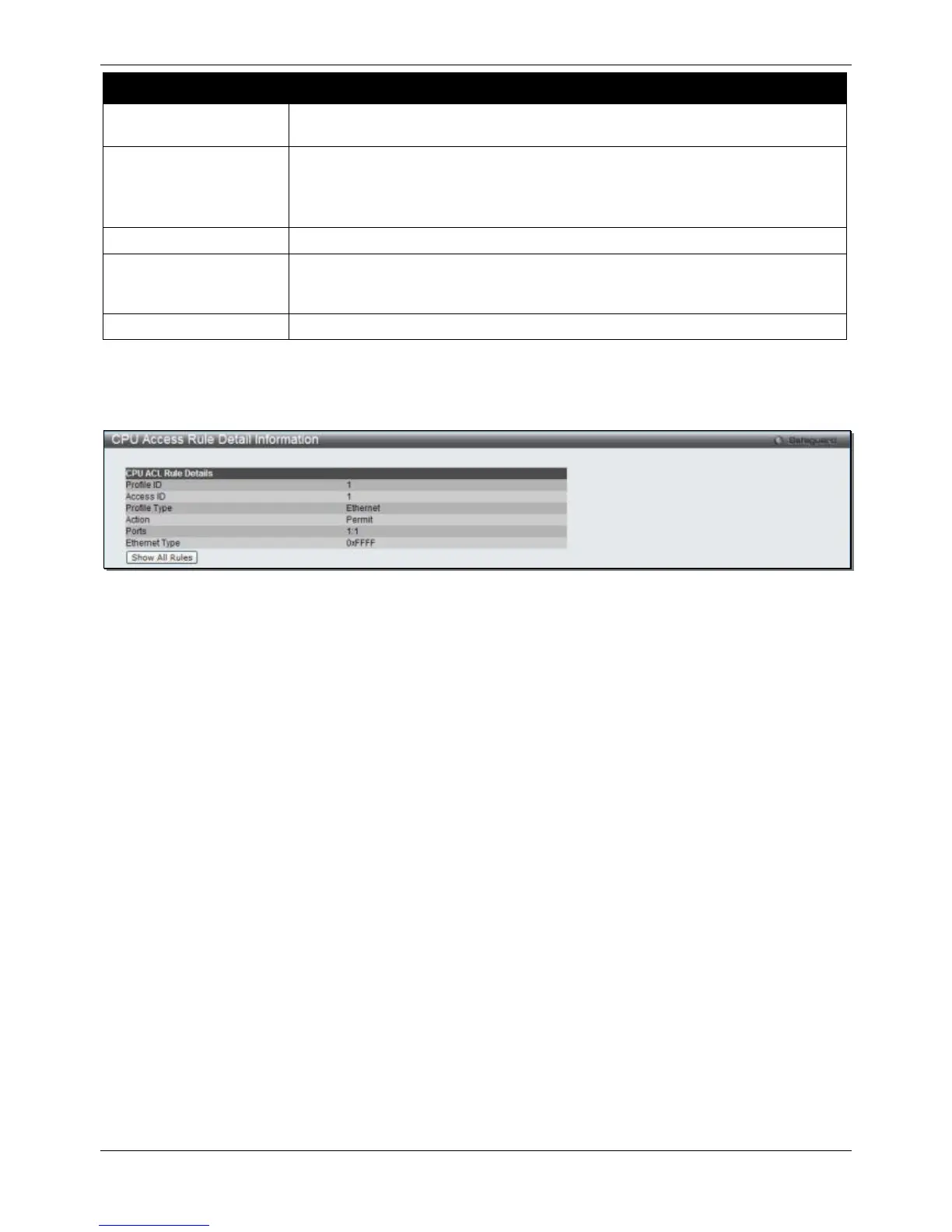
After clicking the Show Details button in the CPU Access Rule List, the following window will appear:
Figure 7-28 CPU Access Rule Detail Information (Ethernet ACL)
Click the Show All Rules button to navigate back to the CPU Access Rule List.
Adding a CPU IPv4 ACL Profile
The window shown below is the Add CPU ACL Profile window for IP (IPv4). To use specific filtering masks in this
ACL profile, click the packet filtering mask field to highlight it red. This will add more filed to the mask.
After clicking the Add CPU ACL Profile button, the following window will appear:
 Loading...