xStack® DGS-3120 Series Layer 3 Managed Gigabit Ethernet Switch Web UI Reference Guide
402
6 Module: For a standalone switch, the Module is always 0; for a stackable switch, the Module is the Unit ID.
7 Port: The incoming port number of the DHCP client packet, the port number starts from 1.
Remote ID sub-option format:
Figure 9-3 Remote ID Sub-option Format
• Sub-option type
• Length
• Remote ID type
• Length
• MAC address: The Switch’s system MAC address.
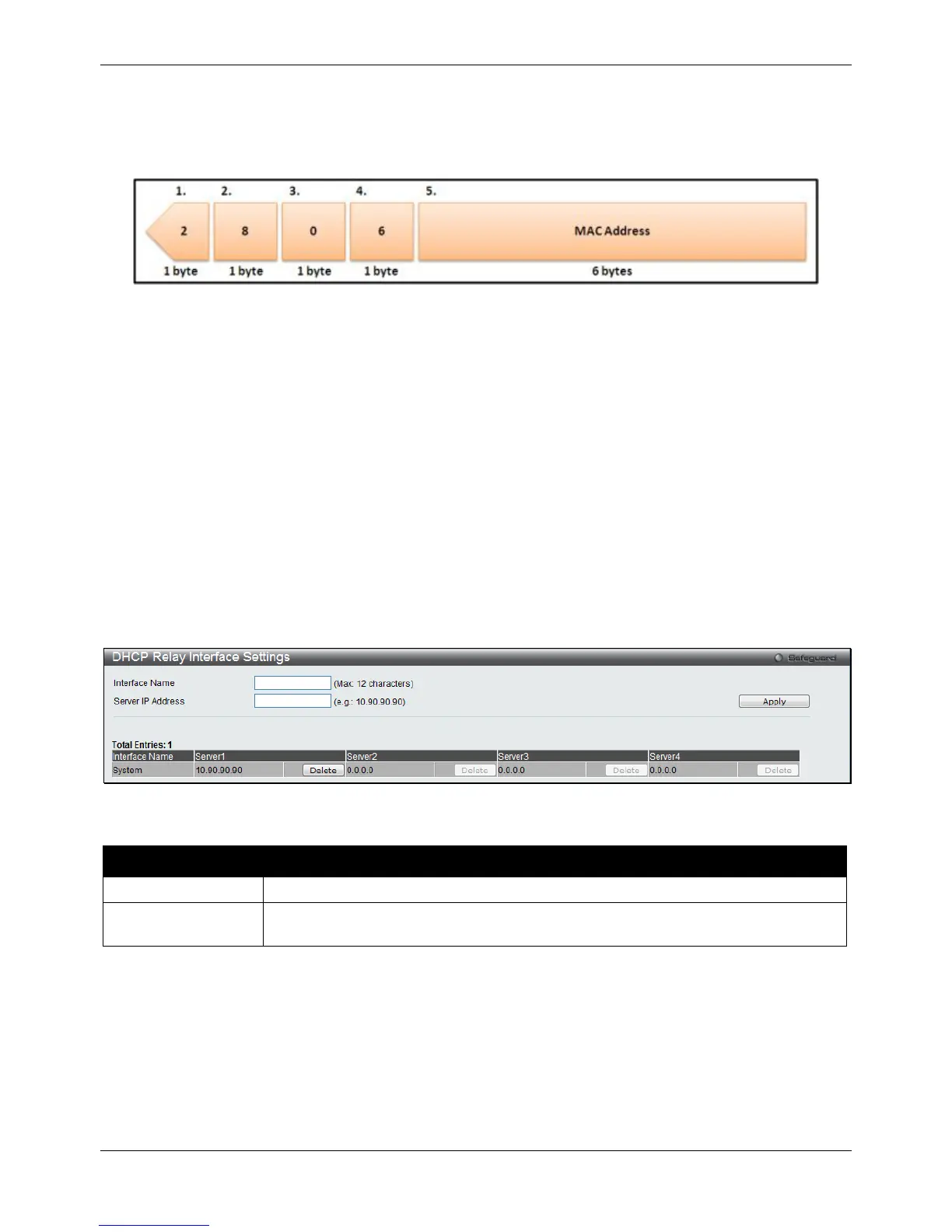
DHCP Relay Interface Settings
This window is used to set up a server, by IP address, for relaying DHCP information to the Switch. The user may
enter a previously configured IP interface on the Switch that will be connected directly to the DHCP server using
this window. Properly configured settings will be displayed in the DHCP Relay Interface Table at the bottom of the
window, once the user clicks the Apply button. The user may add up to four server IPs per IP interface on the
Switch. Entries may be deleted by clicking the corresponding Delete button.
To view this window, click Network Application > DHCP > DHCP Relay > DHCP Relay Interface Settings as
shown below:
Figure 9-4 DHCP Relay Interface Settings window
The fields that can be configured are described below:
Parameter Description
Click the Apply button to accept the changes made.
Click the Delete button to remove the specific entry.
DHCP Relay VLAN Settings
This window is used to configure an IP address as a destination to forward (relay) DHCP/BOOTP packets. If there
is an IP interface in the VLAN and it has configured a DHCP server at the interface level, then the configuration at
the interface level has higher priority. In this case, the DHCP server configured on the VLAN will not be used to
forward the DHCP packets.
 Loading...