xStack® DGS-3120 Series Layer 3 Managed Gigabit Ethernet Switch Web UI Reference Guide
247
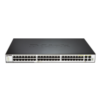
Figure 5-138 PIM for IPv6 Multicast Route S-G RPT Table – View Detail window
VRRP (RI Mode Only)
Virtual Routing Redundancy Protocol (VRRP) is a function on the Switch that dynamically assigns responsibility for
a virtual router to one of the VRRP routers on a LAN. The VRRP router that controls the IP address associated with
a virtual router is called the Master, and will forward packets sent to this IP address. This will allow any Virtual
Router IP address on the LAN to be used as the default first hop router by end hosts. Utilizing VRRP, the
administrator can achieve a higher available default path cost without needing to configure every end host for
dynamic routing or routing discovery protocols.
Statically configured default routes on the LAN are prone to a single point of failure. VRRP is designed to eliminate
these failures by setting an election protocol that will assign a responsibility for a virtual router to one of the VRRP
routers on the LAN. When a virtual router fails, the election protocol will select a virtual router with the highest
priority to be the Master router on the LAN. This retains the link and the connection is kept alive, regardless of the
point of failure.
To configure VRRP for virtual routers on the Switch, an IP interface must be present on the system and it must be a
part of a VLAN. VRRP IP interfaces may be assigned to every VLAN, and therefore IP interface, on the Switch.
VRRP routers within the same VRRP group must be consistent in configuration settings for this protocol to function
optimally.
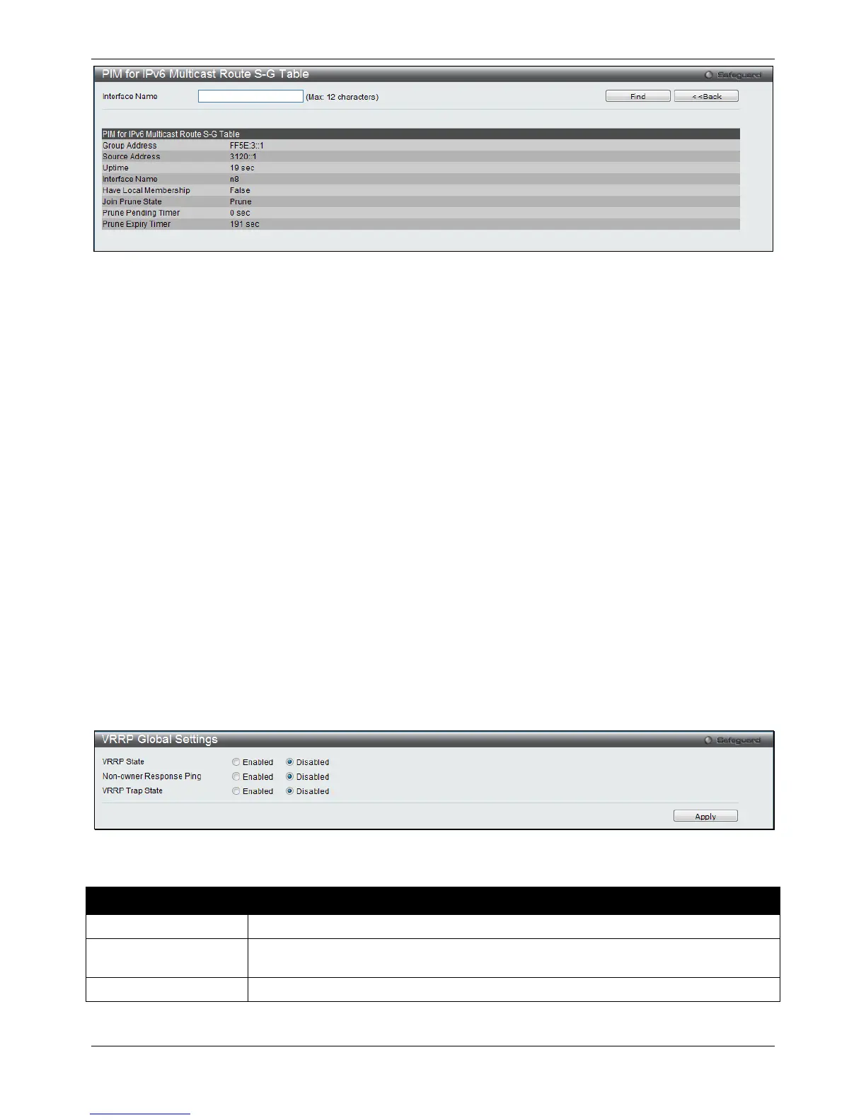
VRRP Global Settings
This window is used to configure the VRRP Global settings for this switch.
To view the following window, click L3 Features > VRRP > VRRP Global Settings, as shown below:
Figure 5-139 VRRP Global Settings window
The fields that can be configured are described below:
Parameter Description
 Loading...