Home
New Holland
Mini Skid Steers
LS160
New Holland LS160 User Manual
5
of 1
of 1 rating
741 pages
Give review
Manual
Specs
To Next Page
To Next Page
To Previous Page
To Previous Page
Loading...
SECTION 10 - ENGINE
10-1
18
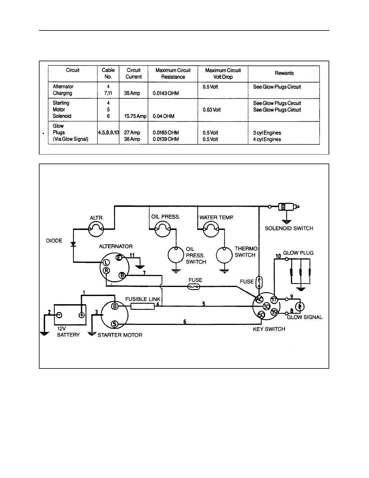
MAXIMUM CIRCUIT RESIST
ANCE
RESIST
ANCE OF BA
TTERY CABLES 1, 2, & 3 NOT T
O EXCEED 0.0018 OHM
19992989
208
19992988
* *
*
209
*
Maximum current draw for oil pressure switch is
0.42 amps (5-watt max. bulb).
**
Diode capacity: Current 3 amp. Reverse voltage
600 volt.
153
155
Table of Contents
Contents
1
Model Codes
3
Safety Information
4
Avoid Heating Near Pressurized Fluid Lines
7
Handle Fluids Safety
7
Use Care Around High-Pressure Fluid Lines
7
Use Care in Handling and Servicing Batteries
7
Controls
8
Safe Service Procedures
8
Machine Model and Serial Number Location
9
Hardware Identification
10
Minimum Hardware Tightening Torques
10
Installation of Adjustable Fittings in Straight Thread O Ring Bosses
12
Standard Torque Data for Hydraulic Tubes and Fittings
12
Lubricants and Coolants
13
Pipe Thread Fitting Torque
13
Sealants
13
Properly Support a Raised Machine
14
Properly Support Boom on Boom Lock Pins
14
Raising Boom Without Hydraulic Oil Flow
14
Raising Boom Without Battery Voltage (12 Volts)
16
Reattaching Cylinders after Repair with Boom Resting on Boom Lock Pins
17
Major Unit Overhaul
18
Cab and Boom Tilt Procedure
19
Craning the Skid Steer
25
Special Tools Table
28
General Information
29
Basic Weight
31
Operating Capacity
31
Tire Sizes and Inflation
31
Specifications
32
Dimensions
35
Table of Contents
37
Engine
37
Crankshaft
39
Cylinder Block
39
Engine Component Descriptions
39
General Description
39
General Engine Information
39
Camshaft
40
Cylinder Head
40
Lubricating System
40
Pistons and Connecting Rods
40
Engine Model and Serial Number Location
41
Turbocharger Lubrication
41
Safety Precautions - Engine
42
General Engine Specifications
43
Engine Troubleshooting
47
Engine will Crank but Does Not Start
47
Engine will Not Crank or Start
47
Irregular Running of the Engine
47
Engine Stops During Operation
48
Faulty Charging
48
Overheat of the Engine
48
Starter Motor Does Not Run
48
Excessive Smoke/Engine Miss
49
Oil Pressure Lamp Not Turned On/Off
49
Engine Noise/Whistling
50
Engine Runs - no Power for Transmission
50
Excessive Oil Consumption (or Oil Smoke from Exhaust)
50
Turbocharger Bearing Failures
50
LS170 - Excessive Oil Consumption
51
Engine Specifications
53
Torque Specifications
57
Engine Components Electrical Diagram
58
Engine Removal
59
Engine Disassembly Sequence
64
Engine Component Maintenance
72
Rocker Assembly
72
Cylinder Head Assembly
73
Valve Guide and Valve Stem
74
Thickness of Valve Head
74
Valve to Valve Guide Clearance
74
Valve Seat
75
Lapping of Contact Face of the Valve Seat
76
Valve Spring
76
Cylinder Block Maintenance
77
Piston and Piston Rings
78
Connecting Rod
81
Bearing Holder
83
Crankshaft Bearing (Bushing)
84
Thrust Clearance
84
Crankshaft Bushing Replacement
85
Crankshaft Journal (Bushing)
85
Crankshaft Maintenance
86
Camshaft Assembly
88
Flywheel and Ring Gear
88
Camshaft Gear and Bearing Assembly
89
Timing Gear
89
Oil Pump
90
Oil Filter
91
Thermostat Removal
91
Water Pump Assembly and Thermostat Housing
91
Governor
93
Governor Operation
95
Engine Reassembly Sequence
97
Crankshaft and Bearing Holder Assembly
98
Rear Oil Seal
98
Backplate/Flywheel Housing
99
Piston and Connecting Rod
99
Idler Gear and Oil Pump Assembly
100
Oil Intake and Oil Strainer
100
Oil Sump
100
Dipstick and Tube
100
Front Plate
100
Crankshaft Pulley
102
Injection Pump Installation
102
Timing Gear Case Installation
102
Adjusting the Fuel Injection Timing
103
Spill Timing Procedure
104
Oil Pipe
108
Cap, Push Rod, and Rocker Arm Assembly
109
Valve Clearance Adjustment
109
Cylinder Head Cover
109
Connect the Thermostat Housing and Hoses
110
Nozzle/Holder Assembly
110
Return Pipe and Injection Pipe
110
Alternator Assembly
110
Reinstallation of Engine into Skid Steer Frame
111
How to Operate the Engine after Overhaul
113
Cooling System Operation
114
Water Pump Assembly and Thermostat Housing
115
Radiator
116
Fuel System
118
Fuel Specifications
118
Diesel Fuel Storage
118
Fuel System Components
119
Filling the Tank
119
Fuel Guage
120
Cold Start Aid
121
Fuel Filter System
121
Priming the Fuel System
122
Fuel System Testing
123
Fuel Flow
125
Fuel Tank
126
Fuel System Components
126
Fuel Lever Sender
127
Fuel Tank Pickup Tube
127
Electric Fuel Pump
127
Governor Description
128
Nozzle and Holder
130
Air Cleaner Description
132
Fuel Injection Timing
132
Turbocharger - LS170 N844T Engine
137
Turbocharger Description
137
Turbocharger Troubleshooting
137
Turbocharger Removal
139
Turbocharger Disassembly
141
Turbocharger Reassembly
146
Checking the Rotor for Movement
149
Turbocharger Lubrication System
150
Glow Plug
152
Miscellaneous Engine Electrical
152
Fuel Shut-Off Solenoid
153
Oil Pressure Switch
153
Maximum Circuit Resistance
154
Special Tools
155
Engine Overhaul
156
Engine Removal from Skid Steer
156
Labor Guide (Engine)
156
Oil Consumption Rectification
156
Rear Drive Axle (Gearboxes)
161
Gearboxes Specifications
164
Final Drive System
165
Gearboxes Troubleshooting
165
Gearboxes Testing
167
Gearboxes Removal and Inspection
168
Gearbox Disassembly
172
Gearbox and Related Parts
173
Gearbox Reassembly
174
Gearbox Reinstallation
176
Reassemble the Parking Brake
177
Gearboxes - Labor Guide
179
Hydrostatic Transmission
181
Neutralizer, Pumps, Motors
181
General Information
183
Operation
183
The Hydrostatic System Components View
184
The Hydrostatic System Specifications
185
The Hydrostatic System Troubleshooting
186
Hydrostatic Drive System Testing
188
Hydrostatic System Oil Flow
191
Hydrostatic Pump and Motor Charge Pressure Oil Flow
192
Hydrostatic Pump and Motor Case Drain Flow
193
Hydrostatic Charge System Pressure Test
194
Hydrostatic Pump Case Drain Test
195
Pump Case Drain (Oil Flow) Test Procedure
197
Hydrostatic Pump High Pressure Test
198
Hydrostatic Pump Efficiency Test
200
Hydrostatic Motor Case Drain Test
202
Hydrostatic Motor Efficiency Test
203
Hydraulic, Hydrostatic System Air Ingress Test
205
Hydrostatic Pumps Removal
207
Hydrostatic Pumps Disassembly
211
Pump Housings Inspection
216
Pump Shafts Inspection
217
Cam Plates Inspection
218
Piston and Shoe Assemblies Inspection
218
Rotating Group Inspection
218
Piston Block Inspection
219
Replaceable Bearing Plate Inspection
219
Back Plate Inspection
220
Hydrostatic Pumps Reassembly
221
Hydraulic System Pump Installation (Without High Flow)
227
Hydraulic System Pump/High Flow Pump Installation
229
The High Flow Pump Components
230
The Hydraulic System Pump Components
230
Hydrostatic Motor Disassembly
238
Hydrostatic Motor Removal
238
Hydrostatic Motor Disassembly
242
Hydrostatic Motor Parts Inspection
247
Hydrostatic Motor Reassembly
250
Motor Shimming Procedure
252
Hydrostatic Motor Reinstallation
260
Hydraulic System Cleaning Procedure
262
Start-Up Procedure after Rebuild (Pump or Motor Replacement)
264
Hydraulic System Cleaning Procedure
266
Start-Up Procedure after Rebuild (after Pump or Motor Replacement)
269
Charge Check Valve Removal and Replacement
271
Hydrostatic System Controls
272
Steering System
272
Control Linkage Removal
274
Neutralizer Assembly
274
Neutralizer Parts Inspection
274
Neutralizer Removal
274
Control Linkage Parts Inspection
275
Left Control Handle with no Boom Hand Control
278
Left Control Handle with Boom Hand Control
281
Right Control Handle with Auxiliary or Bucket Control
287
Bucket Control Handle
289
Drive Control Adjustment Procedure
296
Neutral Adjustment
297
Control Lever Parallel Adjustment
298
Control Lever Stop Adjustment
298
Hydrostatic System and Steering System Labor Guide
299
Brakes and Controls
300
Parking Brake
300
General Information
301
Brakes and Controls Specifications
303
Brakes and Controls Troubleshooting
304
Parking Brake Testing
306
Parking Brake Operation
307
Parking Brake Removal and Inspection
308
Brake Control Linkage Removal
309
Parking Brake Control Linkage and Related Parts
310
Inspection of Control Linkage Parts
311
Installation of Brake Control Linkage
312
Spring Reassembly
312
Brake Caliper and Disc Removal
313
Brake Caliper and Disc Parts Inspection
314
Brake Caliper and Disc Reassembly
316
Parking Brake and Linkage Adjustment
319
Spring Adjustment
319
Caliper Adjustment
320
Brakes and Controls Labor Guide
321
Hydraulic System
322
Valves, Gear Pump, Cylinders, and Pedal Controls
322
General Information
324
Hydraulic System Compatibility
325
Boom and Cylinder Pivot Pin Location and Machine Usage
327
Boom Cylinder Pivot Pins
327
Control Valve Power Beyond
328
Hydraulic System Specifications
329
Hydraulic System Troubleshooting
333
Auxiliary Boom Hydraulics Troubleshooting
337
Adjustments Control Handle
338
Hydraulic System Testing
339
Hydraulic System Oil Flow
345
Control Valve - Bucket Spool Shifted
346
Control Valve - Boom Spool Shifted
347
Auxiliary Control Operation
348
Control Valve - Auxiliary Spool Shifted
348
Main System Pressure Tests
349
Checking Main System Pressure at Boom Cylinders
351
Checking Main System Pressure at Bucket Cylinders
352
Check Main System Pressure at Auxiliary Boom Hydraulic Quick Couplers
353
Boom Circuit Relief Valve Test
354
Gear Pump Flow Efficiency Test
356
Boom and Bucket Spool Lock Solenoid Test
360
Hydraulic, Hydrostatic System Air Ingress Test
362
Control Valve Specifications
364
Control Valve Removal
365
Control Valve Disassembly and Inspection
366
Main System Relief Valve
366
Lift Check Valves
367
Spool Locks (Boom and Bucket)
367
Spools, Caps, and O Rings
368
Control Valve Parts Inspection
370
Control Valve Reassembly
371
Control Valve Reinstallation
374
Hydraulic Pump Specifications
375
Hydraulic Pump Removal
376
Hydraulic System Pump and High Flow Pump Removal/Disassembly
377
Hydraulic System Pump Removal/Disassembly (Without High Flow)
377
High Flow Pump Parts Inspection
379
Hydraulic System Pump Parts Inspection
380
Hydraulic System Pump Reassembly/Installation (Without High Flow)
382
Hydraulic System Pump and High Flow Pump Reassembly/Installation
385
New Hydraulic System Pump Installation (Without High Flow)
391
New Hydraulic System Pump/High Flow Pump Installation
393
Gear Pump Start-Up Procedure
399
Boom Cylinders Specifications
400
Cylinders, Boom and Bucket
400
Boom Cylinder Disassembly
402
Boom Cylinder Removal
402
Boom Cylinder Disassembly
404
Boom Cylinder Parts Inspection
405
Boom Cylinder Reassembly
406
Boom Cylinder Reinstallation
408
Bucket Cylinder Disassembly
408
Bucket Cylinder Removal
408
Bucket Cylinder Disassembly
409
Bucket Cylinder Parts Inspection
410
Bucket Cylinder Reassembly
411
Bucket Cylinder Reinstallation
413
Pedal Controls Removal
414
Pedal Inspection (with Boom and Bucket Pedal Controls)
414
Pedal Reinstallation (with Boom and Bucket Pedal Controls)
416
Pedal Removal (with Boom and Bucket Hand Controls)
419
Pedal Inspection (with Boom and Bucket Hand Controls)
420
Pedal Reinstallation (with Boom and Bucket Hand Controls)
421
Hydraulic Cooling, Filter, Reservoir System
424
Filter Base Removal
425
Filter System
425
Filter Base Reassembly
426
Oil Cooler Removal
426
Filter/Breather Cap Cleaning
427
Oil Cooler Reassembly
427
Oil Reservoir
427
Oil Reservoir Removal
428
Oil Reservoir Reinstallation
429
Adapting Attachments with NH-Supplied Ball/Pin Couplers
430
Hydraulic System Labor Guide
431
Rear Counterweights
432
Towing Hooks and Ballasting
432
Frames
434
Lower Main, ROPS
434
ROPS Frame Removal
435
ROPS Frame Reinstallation
441
Frames Labor Guide
444
Axles and Wheels
446
Axles Specifications
449
Axles Troubleshooting
450
Final Drive System Troubles
450
Final Drive Testing
452
Axle Housing Assembly Removal
453
Axle Housing Assembly Disassembly
454
Axle Housing Assembly Parts Inspection
456
Axle Housing Assembly Reassembly
457
Axle Housing Assembly Reinstallation
459
Drive Chain and Sprocket Removal
460
Brake Disc Removal
462
Front Drive Sprocket and Chain
463
Proper Tire Inflation
467
Tire Options
467
Tire Pressures
467
Tires/Wheels
467
Tire and Track Installation
468
Track Installation on Loader
468
Axles Labor Guide
469
Cab Climate Control
470
Heater/Defroster
470
Heater/Defroster (CAB)
471
Relay and Fuse Block
471
Switch and Control Panel
471
Switch Wiring
471
Heater Wiring Diagram
472
Louver Replacement
472
Heater Core Replacement
473
Heater Core, Shutoff Valve and Fan Assembly Access
473
Heater Shutoff Valve Replacement
473
Heater Fan Assembly Replacement
474
Heater Hose to Engine Connections
474
Filter (Heater)
475
Heater Core Connections
475
Bleeding Air from Heater
476
Heater/Defroster Labor Guide
477
Advanced Warning System, Circuits, Alternator, and Starter
478
Electrical System
478
General Electrical Information
483
Electrical System - Definition of Terms
484
Wire Abbreviations to Indicate Wire Color
485
Adapting Attachments Requiring 12V Electrical Power
486
Engine Fuse Panel
487
Electrical System Specifications
489
Electrical Diagram
492
Advanced Warning System
496
Electronic Instrument Cluster (EIC)
496
(EIC) Electronic Instrument Cluster Front Panel
497
EIC Functional Groups
498
Continuously Monitored Elements
502
Automatic Shutdown
503
Engine Preheat
503
Operating Mode
504
Broken Alternator/Water Pump Belt Warning
506
EIC Interlocks
507
Fuel Level
507
EIC Lock Mode
508
EIC Engine Preheat
509
Electronic Instrument Cluster (EIC) Troubleshooting
510
Advanced Warning System (AWS)
513
EIC Board Self Test
514
Diagnostic and Setup Modes
515
EIC Diagnostics and Setup Items
516
Arrow, Open Book, and Audible Alarm Test
517
Diagnostic Mode EIC Circuit Tests
517
Hydraulic Oil Filter Restriction Switch
517
Air Cleaner Switch
518
Engine Oil Pressure Sensor
518
Hydrostatic Charge Pressure Switch
518
Coolant Temperature Sensor
519
Fuel Gauge
519
Transmission/Hydraulic Oil Temperature Sensor
519
Seat Belt Switch and Circuit
520
Seat Switch and Circuit
520
Service/Run Switch
520
EIC Setup Mode
521
Eng 0 0 - Engine Code
526
R-CAL - Adjust Engine RPMS
527
Unit F or Unit C (EIC Reading Fahrenheit or Celsius)
527
Blown Fuse Symptom and Testing
529
Electronic Battery Fuse
529
Electronic Instrument Cluster (EIC) and Starter Circuits
529
Key Main Fuse
529
Parking Brake Light Testing
531
Seat Belt Light Testing
531
Testing Other EIC Functions
531
Boom and Bucket Spool Locks Testing
532
EIC Board Reading Accuracy
534
EIC Board Claims Warranty
536
Handling the EIC Board
536
EIC (Electronic Instrument Cluster)
537
EIC Board Ground Circuit
537
Electrical Circuits
537
Main Power Circuit to EIC Board
537
Battery Voltage
538
Seat Switch Circuit to EIC Board
538
Seat Belt Switch Circuit to EIC Board
539
Ignition Switch Circuit to EIC Board
540
Cranking Circuit (Starter Motor)
541
"Service/Run" Switch in the "Run" Position
542
Crankging Circuit Ground
543
Operating Conditions "Service/Run" Switch in the "Service" Position
543
Service/Run Switch in the "Service" Position
544
Cranking Circuit Ground
545
Start Relay Operation
545
Start Relay Circuit
546
Start Interlock Relay Operation
547
Start Relay Ground Circuit
547
Start Interlock Circuit
548
Start Circuit
549
Start Interlock Ground Circuit
549
Removal, Installation and Wiring of Electrical Components
550
Battery Removal
551
EIC (Electronic Instrument Cluster) Board Removal
552
EIC (Electronic Instrument Cluster) Wiring
553
EIC (Electronic Instrument Cluster) Board Installation
554
Ignition (Key) Switch Wiring
555
Cab Fuse Panel Wiring
556
Cab Fuse Block and Panel Removal and Installation
557
Service/Run Switch - Run Position
558
Service/Run Switch - Service Position
558
Service/Run Switch Wiring
558
Service/Run Switch Removal and Installation
559
Seat and Swat Belt Switch Wiring
560
Seat Switch Removal
560
Seat Belt Buckle and Switch Assembly Removal
561
Seat Belt Buckle Installation
561
Seat Switch Installation
561
Road Light and Work Light Switch Wiring
562
Road Light and Work Light Switch Removal and Installation
563
Engine Fuse and Relay Panel
564
Accessory Relay Removal and Installation
565
Accessory Relay Wiring
565
Preheat Circuit Breaker Removal and Installation
566
Preheat Circuit Breaker Wiring
566
Start Interlock Relay Wiring
567
Start Interlock Relay Installation
568
Start Interlock Relay Removal
568
Engine Fuse Panel Wiring
569
Engine Fuse Block Installation
570
Engine Fuse Block Removal
570
Alternator Excite Resistor Removal and Installation
571
Alternator Excite Resistor Wiring
571
Start Relay Removal and Installation
572
Start Relay Wiring
572
Preheat Relay Wiring
573
Preheat Relay Removal and Installation
574
Preheat Glow Plug Removal and Installation
575
Fual Gauge
576
Fuel System Electrical Diagram
576
Fuel Tank Sending Unit (Fuel Level)
576
Removal of Fuel Lever Sender
577
Testing Fuel Gauge in Diagnostic Mode
577
Testing of the Fuel Level Sender
577
Electric Fuel Pump Testing
578
Electric Fuel Pump Removal
579
Fuel Shutoff Solenoid Testing
579
Fuel Shutoff Solenoid Replacement
580
Air Filter Restriction Indicator Switch Removal
581
Engine Coolant Temperature Sender Removal and Installation
581
Engine Oil Pressure Switch Removal and Installation
582
Hydrostatic Charge Pressure Switch Removal and Installation
582
Hydraulic Oil Filter Restriction Switch Removal and Installation
583
Hydraulic Oil Temperature Sender Removal and Installation
583
Boom/Bucket Control Valve Spool Lock Solenoids
585
Boom/Bucket Control Valve Spool Lock Solenoids Installation
585
Boom/Bucket Control Valve Spool Lock Solenoids Removal
585
Main Wire Harness Removal
587
Main Wire Harness Installation
592
Road/Work Lights
596
Road/Work Light Switch Wiring
597
Road/Work Light Wiring Diagram
597
Rear Work and Taillight
599
Alternator (40 Amp Version)
600
Alternator Charging Circuit
600
Alternator Service Specifications
602
Alternator System Testing and Troubleshooting
603
Alternator Construction
605
Checking the Regulator Adjusting Voltage
605
Sectional View of the IC Alternator
605
Alternator Removal
607
Alternator Disassembly
608
Alternator Component Test
610
Stator Test
611
Diode Trio Test
612
Negative Heat Sink Test
612
Positive Heat Sink Test
612
Rectifier Assembly
612
Brush and Brush Spring Check
613
Installing Rotor
613
Bench Check
614
Alternator Reinstallation
615
Starter Motor Service Specifications
616
Starter Motor Troubleshooting
616
Starter Motor Disassembly
618
Starter Motor Removal
618
Starter Motor Description
619
Starter Construction
620
Starter Operation
621
Drive Spring Operation
622
Electric Solenoid Operation
622
Starter Disassembly
623
Starter Inspection and Repair
627
Field Coil
628
Brushes
629
Overrunning Clutch
630
Reduction Gears
630
Electric Solenoid
631
Pull-In Test
631
Starter Reassembly
632
Starter Performance Test
635
Starter Reinstallation
636
Electrical System Labor Guide
637
Buckets
638
Front Loader (Boom and Mounting Plate)
638
Bucket Capacity Cubic Feet
639
Bucket Types
639
General Information
639
Boom Assembly Components
640
Boom Lock Pins and Linkage
640
Attachment Mounting Plate
641
Boom and Cylinder Pivot Pin Location and Machine Usage
641
Boom/Cylinder Pivot Pins Size
642
Pallet Fork
643
Tine Installation
644
Utility Fork
644
Buckets - Cutting Edge (Replacement)
645
Bucket Latch Plate Installation Procedure
646
Dirt Tooth Kit Installation
648
Tooth Location and Installation
649
Tooth Point Replacement
649
Bucket Tooth Spacing
650
Boom Lock Pin/Linkage Removal
652
Boom Lock Pin/Linkage Reinstallation
653
Boom, Upper and Lower Link Removal
655
Lower Link Removal
656
Upper Link Removal
657
Main Boom Removal
658
Front Boom Mounting Plate Pivot Hub Replacement
661
Boom, Upper and Lower Link Reinstallation
662
Attachment Mounting Plate
666
Latch Lever and Pin Removal/Repair
667
Repair/Rebuild Mounting Plate
667
Latch Handle/Spring Assemblies
669
Latch Pins
669
Mounting Plate Assembly
669
Pivot Bushings Replacement
669
Latch Lever and Spring Repair/Rebuild
670
Attachment Plate Over-Center Latch Pins Wear/Bend
673
Checking Procedure for Buckets and Attachments
673
Checking Procedure
675
Checking the Attachment
675
Checking the Loader Faceplate
676
Labor Guide
678
Accessories
680
Dealer Installed Options
680
Adapting Attachments Requiring 12V Electrical Power
681
General Information
681
Hydraulic System Compatibility
684
Arm Pads for Cab Side Panels
686
Armrests for Deluxe Seat
686
Forearm Rests
687
Back-Up Alarm
688
Block Heater (Engine)
689
Electric Power Supply (12 Volt, 15 Amp)
690
Electric Power Wiring
690
Aspirator Precleaner Muffler
691
Catalytic Muffler
691
Exhaust (Engine)
691
Aspirator or Spark Arrester Muffler Cleaning
692
High Flow Hydraulics
693
Attachment Case Drain
694
High Flow Hydraulics Troubleshooting
695
High Flow Hydraulics Component Replacement
697
High Flow Pump Removal / Disassembly
698
High Flow Pump Reassembly / Installation
700
High Flow Electrical Wiring Diagram
703
High Flow Hydraulic Oil Flow Diagram
703
Horn
704
Shoulder Belt (Seat)
705
Slow-Moving Vehicle (SMV) Sign Kit
706
Warning Light (Rotary Beacon)
707
Beacon Switch Wiring
708
Beacon Wiring Diagram
708
Beacon Bulb Replacement
709
Warning Lights (Four-Way Flashers/Turn Signal/Horn)
710
Warning Light Switch Wiring
711
Warning Light (Four-Way) Wiring Diagram
712
Rear Light
713
Warning Light Bulb Replacement
713
Accessories Labor Guide
714
Cab and Seat
716
Platform, Cab, Bodywork, and Decals
716
General Information
717
Seat and Seat Pan Support
717
Cab Inner Shell
718
Seat Pan Support Removal
718
Seat Removal
718
Seat, Switch and Pan Reinstallation
720
Cab Inner Shell Removal
722
Cab Inner Shell Reinstallation
729
Cab Inner Shell Removed from the Loader ROPS
729
Safety Decals
737
Labor Guide
741
Other manuals for New Holland LS160
Workshop Manual
41 pages
5
Based on 1 rating
Ask a question
Give review
Questions and Answers:
Need help?
Do you have a question about the New Holland LS160 and is the answer not in the manual?
Ask a question
New Holland LS160 Specifications
General
Brand
New Holland
Model
LS160
Category
Mini Skid Steers
Language
English
Related product manuals
New Holland LS170
741 pages

 Loading...