SECTION 35 - HYDRAULIC SYSTEM
35-3
19997771
2
1
6
7
8
9
11
14
14
13
13
11
5
12
12
3
4
14
10
1
Op. 35 000
GENERAL INFORMATION
The hydraulic system provides hydraulic oil to the
boom and bucket, and the return oil provides charge
oil for the hydrostatic drive system. On skid steers
equipped with the auxiliary boom hydraulic kit, sys-
tem oil will be provided to quick couplers at the front
of the boom to operate hydraulic attachments. The
hydraulic system is an open center type system. The
gear pump provides continuous oil flow through the
system to the boom, bucket circuits, auxiliary boom
circuit, if equipped, and the hydrostatic drive charge
circuit.
A open center system means the first control valve
function has priority over the next function in line.
NOTE: The return oil must follow the normal return
path from the control valve to the oil cooler/filter and
back to the hydrostatic charge pressure inlet on the
transmissions or severe damage to the hydrostatic
system may occur.
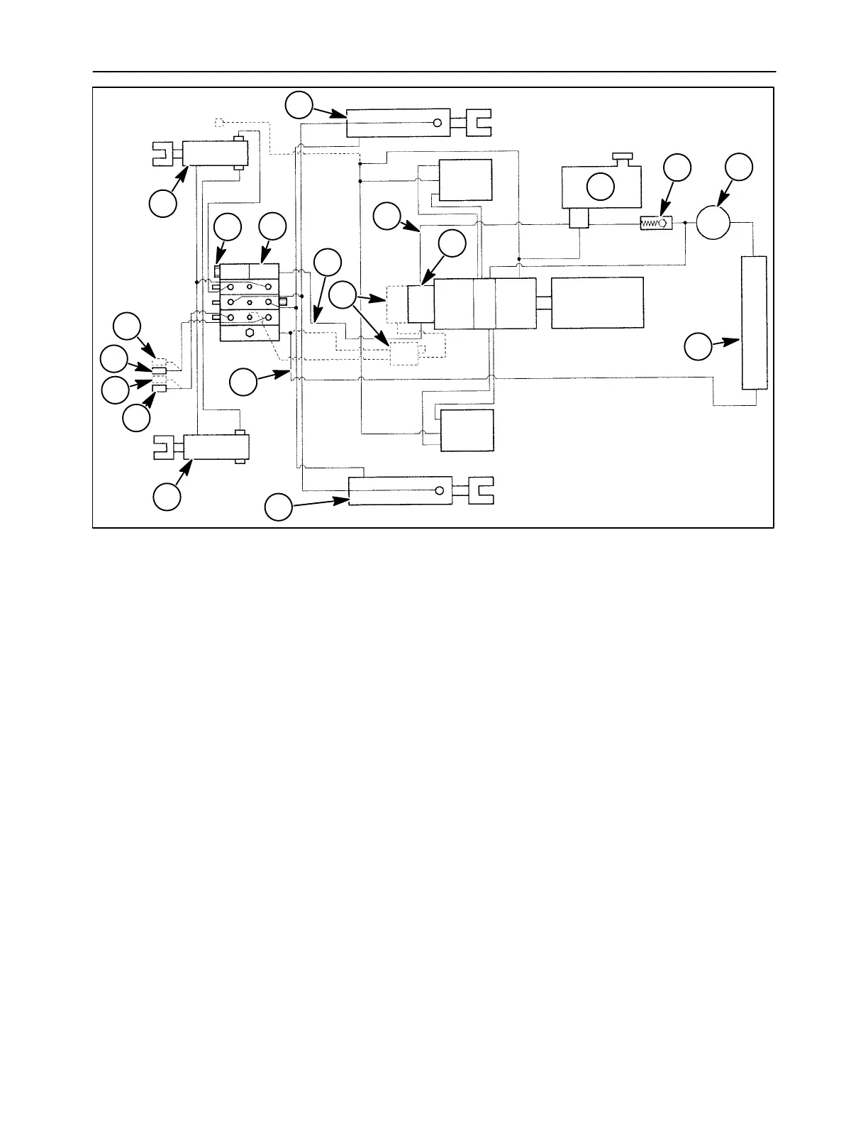
Figure 1 shows the hydraulic circuit and components
for the LS160 and LS170 skid steers.
The hydraulic system is built with the following com-
ponents and their location.
1. Hydraulic reservoir - Right front of engine
compartment
2. Suction line - From reservoir to the gear pump
under operator’s seat
3. Gear pump - Under the operator’s seat
4. Pressure line - From gear pump to control valve
5. Control valve (three spool) - Under operator’s
step shield
6. Main system relief valve - In control valve
7. Return line - From control valve to oil cooler
8. Oil cooler - Engine side of radiator in engine
compartment
9. Filter - Right rear of engine compartment through
rear door
10. Charge check valve - After filter and before the
reservoir
11. Bucket cylinders
12. Boom cylinders
13. Auxiliary boom hydraulics
14. Optional high flow kit - Dealer installed kit - Refer
to Section 88 - “Accessories” for more informa-
tion.
 Loading...