SECTION 10 - ENGINE
10-48
Thrust Clearance
Check the thrust washer for wear, poor contact,
burning, or other defects. Defective washers must be
replaced.
Standard Thickness: 0.116″ - 0.118″ (2.95 mm -
3.0 mm)
Allowable Limit: 0.11″ (2.8 mm)
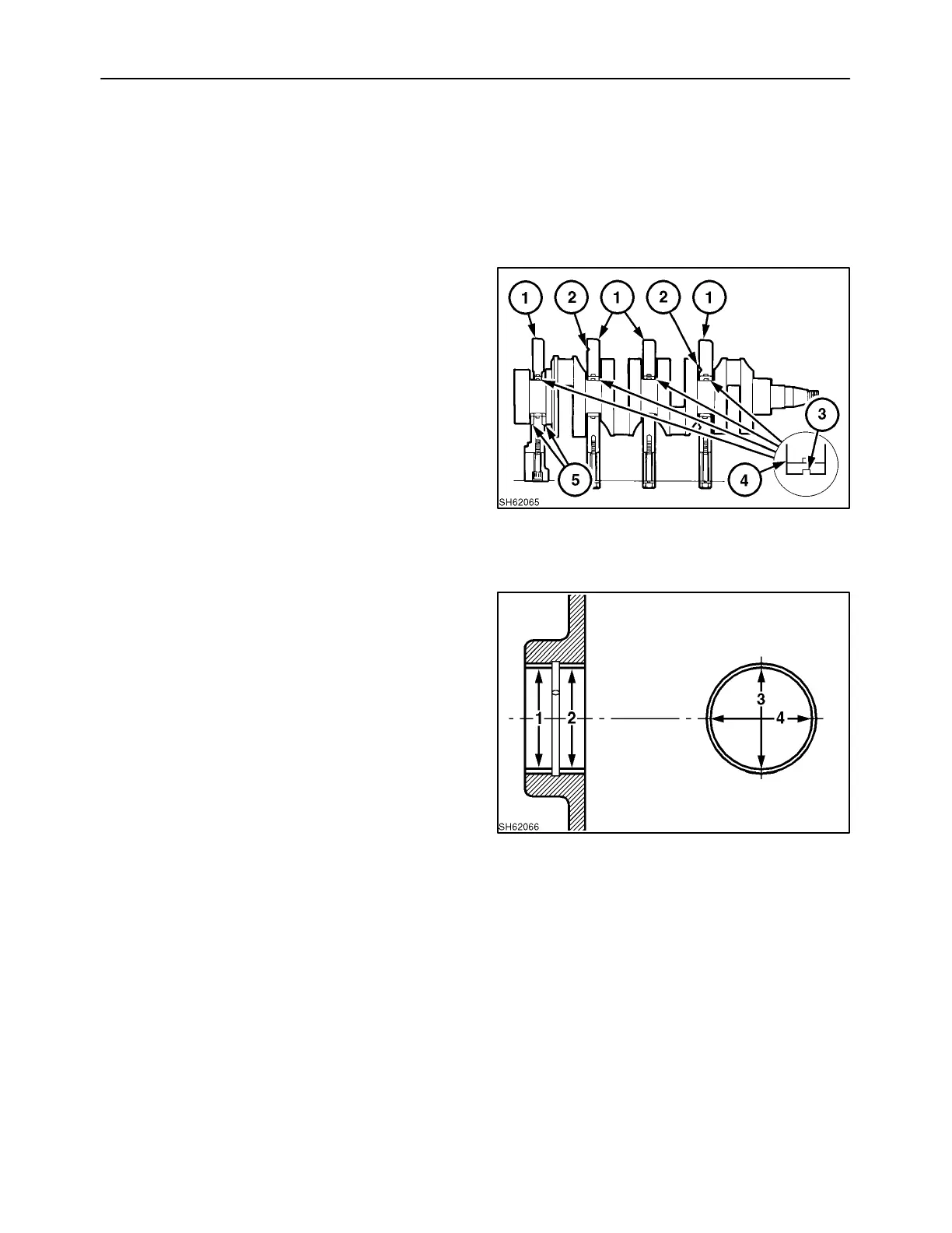
Reassembly
Reassemble the bearing holder, center bearing, and
thrust washer as follows:
1. Face the chamfered part, 1, of the bearing holder
toward the front. Install the bearing holder which
has a notch, 2. Install the bearing holder on which
the thrust washer is to be mounted at the flywheel
side.
2. Install the thrust washer, 5. Face its oil groove
toward the thrust face of the crankshaft.
Tightening torque of the bearing holder: 36 - 40
ft. lbs. (49 - 54 N·m).
3. Set the bearing with the oil groove, 3, to the upper
part, 4, while setting the bearing without the
groove to the lower part.
66
CRANKSHAFT BEARING (BUSHING)
Inspection
Check the bearing (bushing) for peeling, melting,
seizure, or poor contact. If found to be defective,
replace.
Using a cylinder gauge and micrometer, measure the
oil clearance between the bearing (bushing) and the
crankshaft journal.
Measure the inside diameters at positions 1 and 2. At
each position, measure in both directions 3 and 4.
The oil clearance can be obtained by subtracting this
value from the maximum crankshaft journal
diameter.
67

 Loading...