SECTION 10 - ENGINE
10-47
Reassembly
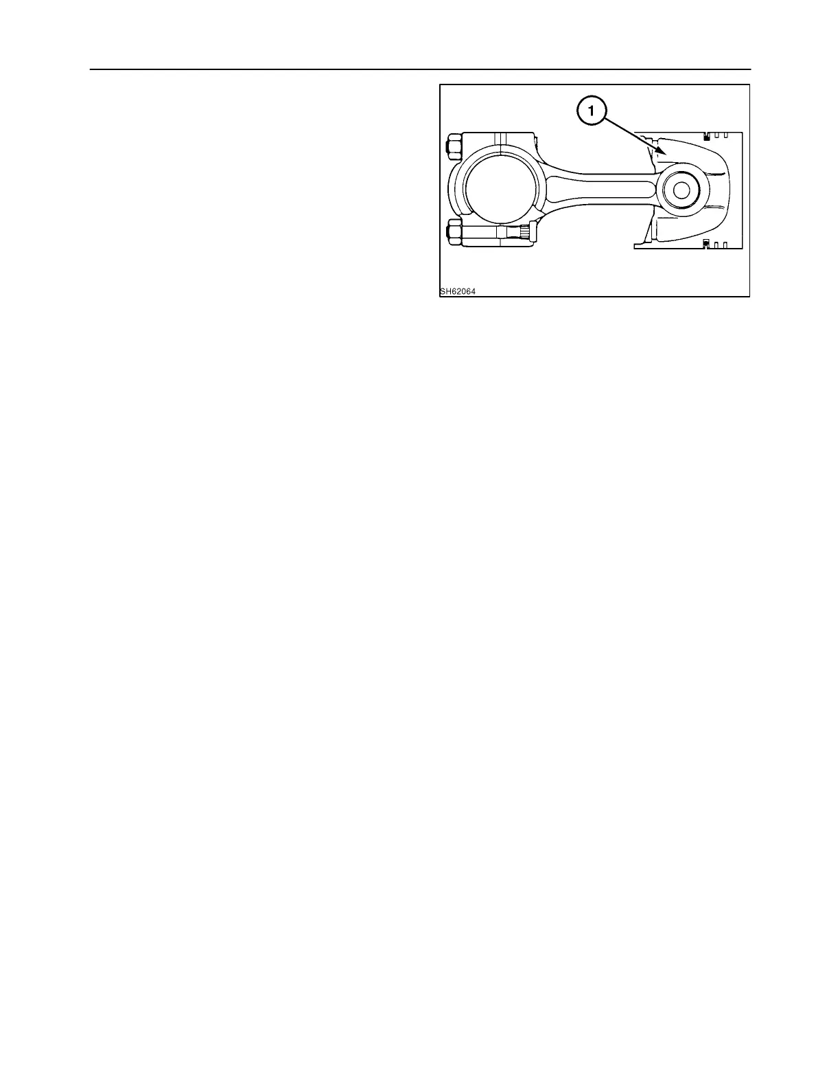
1. Reassemble the piston on the connecting rod as
follows.
2. With a piston heater or the like, heat the piston to
approximately 212° F (100° C). Assemble the
piston to the connecting rod by aligning the set
marks.
3. Set the “SHIBAURA” marks, or other mark, 1, as
shown. Align the set marks on the connecting
rod.
4. Replace the piston ring on the piston. Position
the scribe mark uppermost.
5. When the connecting rod or piston/piston pin has
been replaced, the difference in the weight of the
assembly (connecting rod plus piston rings)
should not exceed 10 grams between cylinders.
Op. 10 103 10
BEARING HOLDER
Disassembly and Inspection
Center Bearing
1. Remove the bearing holder and check it for
peeling, melting, stepped wear, and other
damage. If it is excessively damaged, replace.
2. Using the plasti-gauge, measure the oil
clearance between the crankshaft center journal
and the bearing.
If the oil clearance is more than the allowable
limit, replace the bearing or grind the crankshaft
center journal and use an undersized bearing
(refer to “Crankshaft”).
Standard Oil Clearance: 0.0017″ - 0 .0040″
(0.044 mm - 0.102 mm)
Allowable Limit: 0.0078″ (0.2 mm)
Crankshaft Center Journal Diameter (mm)
S.T.D.: 2.6755″ - 2.6760″ (67.957 mm - 67.970
mm)
0.010″ (0.25 mm): 2.6656″ - 2.6661″ (67.707 mm
- 67.720 mm)
0.020″ (0.50 mm): 2.6558″ - 2.6563″ (67.457 mm
- 67.470 mm)
65
 Loading...