SECTION 35 - HYDRAULIC SYSTEM
35-45
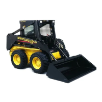
6. Drain the hydraulic reservoir by disconnecting
the return line, 1, at tee, 2, and drain the oil into
a suitable container.
42
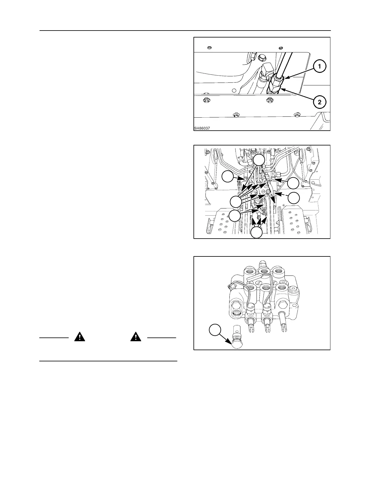
7. Unplug the spool lock solenoids, 1.
8. Remove the pressure line, 2, and return line, 3;
cap both lines to prevent loss of oil and contami-
nation from entering the hydraulic system.
9. Remove the hydraulic lines connected to the
work ports of the control valve, 4, four or six lines,
if unit is equipped with auxiliary boom hydraulics
and cap.
10. Remove the line from the power beyond port, 5,
if equipped with auxiliary hydraulics and cap.
11. Unhook the control linkage from the control valve
spools at 6.
12. Remove the control valve retaining hardware, 7.
Lift the control valve assembly from the loader.
19984464
4
6
2
3
1
7
5
43
Op. 35 724 54
DISASSEMBLY AND INSPECTION
Main System Relief Valve
The non-serviceable, non-adjustable, cartridge- type
main system relief valve, 1, is set at 170 - 177 bar
(2500 - 2600 PSI). The relief valve should not be re-
placed with a valve of a higher pressure setting, as
structural damage to the boom and/or main frame or
internal damage to hydraulic system may occur.
CAUTION
Component failure from high hydraulic pressure
could result in injury.
19984465
1
44
 Loading...