SECTION 33 - BRAKES AND CONTROLS
33-11
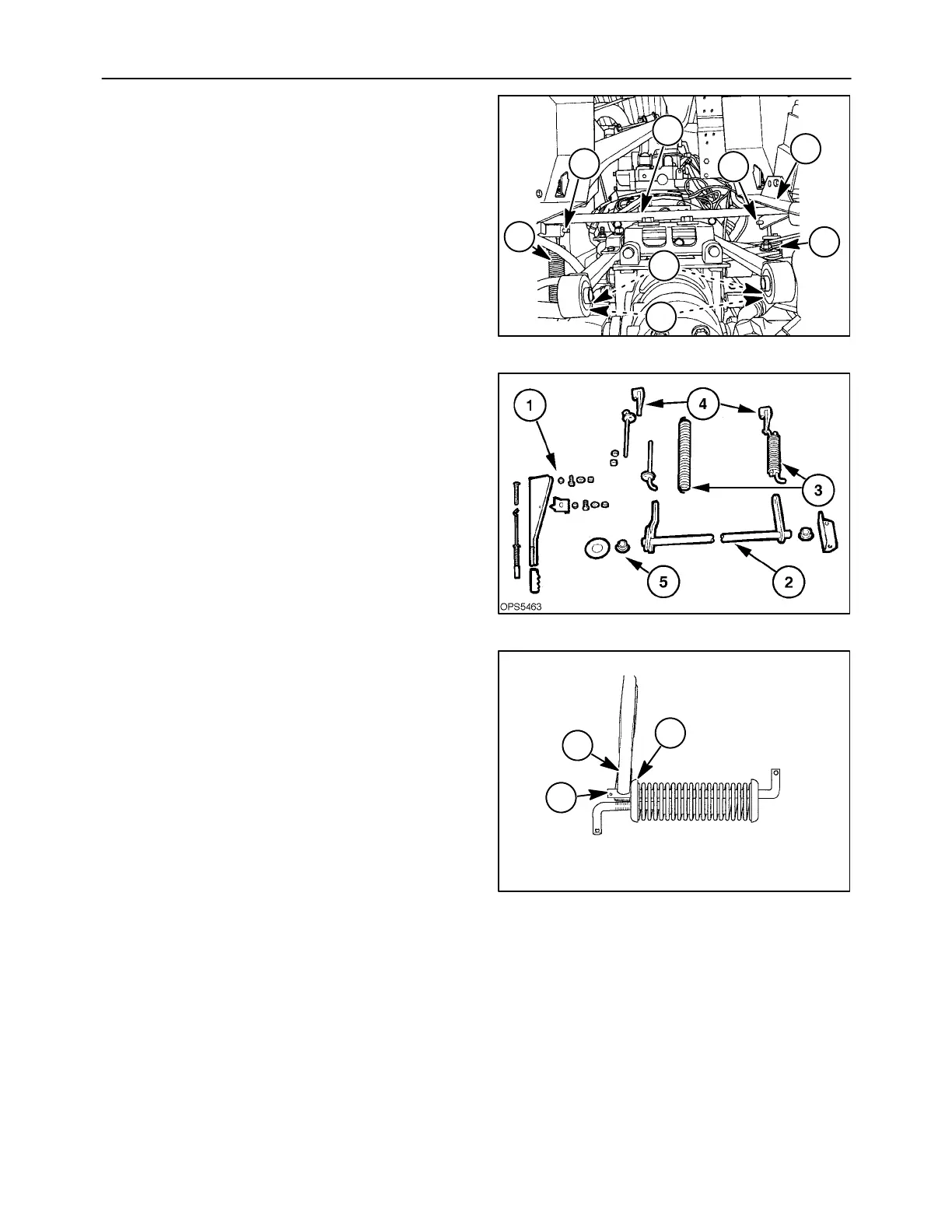
Op. 33 110 30
2. To remove the control rod assembly, 1, remove
the cotter pins from the spring links, 2.
3. Remove the left support bracket and hardware,
3, then pivot the rod assembly down and slide the
control rod from the right support bracket.
Remove the pivot bushings from supports and
friction pad from rod.
4. Remove the lower cotter pin, 4, and remove the
spring assemblies, 5, from the brake caliper ac-
tuator arm, 6.
19992569
1
2
6
2
3
5
5
4
15
Parking Brake Control Linkage and Related
Parts
Ref. Description
1 Control handle and related parts
2 Control shaft, bearings, support
3 Spring assembly
a. Spring
b. Spring links (2)
4 Arm
5 Friction pad
16
Spring Disassembly
1. Compress spring plate and spring, 1, to expose
enough shaft to clamp vise grips, 2.
2. Remove roll pin, 3.
2
1
19995774
3
17

 Loading...