SECTION 35 - HYDRAULIC SYSTEM
35-59
HYDRAULIC SYSTEM PUMP PARTS
INSPECTION
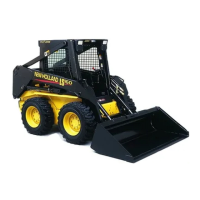
1. Inspect the pump mounting plate for excessive
wear. The oil grooves in the bushings, 1, should
be line up with the dowel pin holes and be
approximately 180° apart. If the bushing oil
grooves are not positioned as noted, the bush-
ings have turned in the plate - the plate should be
replaced.
The bushings in the plate should be 3.20 mm
(0.126″) above the surface of the plate. Replace
the plate if the I.D. of the idler gear bushing ex-
ceeds 19.2 mm (0.755″).
2. Check the seal areas, 2, for scratches or damage
that could prevent a good seal.
19997782
1
2
78
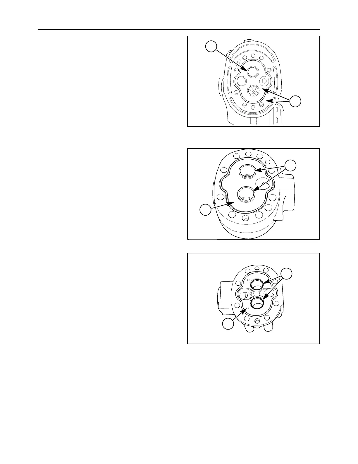
3. With High Flow - Inspect the pump back plate for
excessive wear. The oil grooves in the back plate
bushings, 1, should be at approximately 37° to
the pressure side. If the bushing oil grooves are
not positioned as noted, the bushings have
turned in the plate. The plate should be replaced
under this condition.
The bushings in the plate should be 3.20 mm
(0.126″) below the surface of the plate. Replace
the back plate if the I.D. of a bushing exceeds
19.2 mm (0.755″).
Check for scoring on the face of the back plate,
2. Replace the back plate if wear exceeds 0.038
mm (0.0015″).
19997786
2
1
79
4. Without High Flow - Inspect the pump back plate
for excessive wear. The oil grooves in the back
plate bushings, 1, should be at approximately
37° to the pressure side. If the bushing oil
grooves are not positioned as noted, the bush-
ings have turned in the plate. The plate should be
replaced under this condition.
The bushings in the plate should be 3.20 mm
(0.126″) below the surface of the plate. Replace
the back plate if the I.D. of a bushing exceeds
19.2 mm (0.755″).
Check for scoring on the face of the back plate,
2. Replace the back plate if wear exceeds 0.038
mm (0.0015″).
19997761
2
1
80
 Loading...