SECTION 55 - ELECTRICAL SYSTEM
55-123
Indicator lamp
174
Op. 55 301
ALTERNATOR (40-AMP VERSION)
CHARGING CIRCUIT
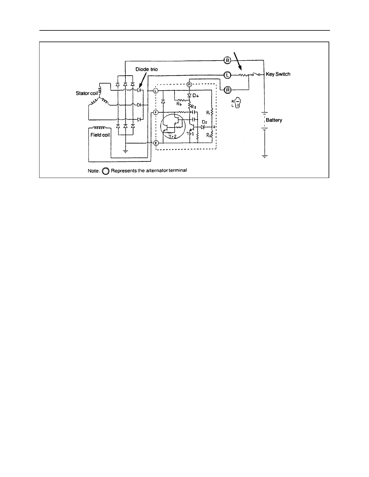
Description
1. The charging circuit and internal connection are
shown here. The charging system consists of an
IC regulator built-in alternator, a battery, and
connecting wires. Because of the use of IC, the
voltage regulator is very compact and is built into
the alternator.
2. The field current flows directly from the diode trio
to the field coil without passing through the
external circuit. Consequently, there are no
voltage drops caused by the key switch or the
wiring, as with the conventional vibrating-contact
regulators mounted separately from the
alternator. To help the initial voltage buildup when
the engine is started, the field current is supplied
through the indicator lamp from the battery.
3. Since the frequency pulse output of 1/10 the
alternator speed develops at “P” terminal, this
terminal is used for speed detection by the EIC
board for engine RPM readings.
Principle of Integrated Circuit Regulator
The basic circuit of the IC regulator is shown here.
The part enclosed by a dotted line represents the IC
regulator.
The basic function of the IC regulator to make
terminal voltage constant by detecting generated
voltage and increasing/decreasing field current is not
different from that of the vibration- contact regulator.
As indicated, the regulator consists of two basic
sections: a voltage control device and an output
device to handle the field current. The voltage control
device includes a voltage divider network (R1, R2),
a Zener diode (DZ) for voltage reference, and a
signal amplifying transistor (Tr1). The output device
is a Darlington-type amplifier which is called power
transistor (Tr2). The transistor Tr2 is placed in series
with the alternator field coil and ground.
The transistor Tr1 senses the generated voltage and
turns the transistor Tr2 on and off many times per
second most of the time the engine is in operation.

 Loading...