SECTION 82 - FRONT LOADER (BOOM AND MOUNTING PLATE)
82-3
Op. 82 100 77
BOOM LOCK PINS AND LINKAGE
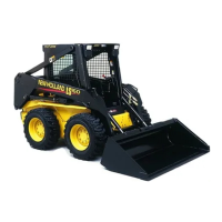
The operator can engage the boom lock pins from
the operator’s seat. The control is located to the right
rear of the operator’s seat at 1. Pivoting the handle
towards the outside of the cab extends and engages
the lock pins. Pivoting the handle in will retract the
lock pins.
2
To engage the boom lock pins:
1. Raise the boom above the boom lock pins and
engage the pins.
2. Turn the ignition key to the “OFF” position to stop
the engine.
3. Turn the ignition key to the “ON” position and op-
erate the boom and bucket hydraulic controls to
lower the boom until it rests on the lock pins, 1,
and relieves pressure in the boom and bucket hy-
draulic circuits.
4. Turn the ignition key to the “OFF” position.
CAUTION
Never work under a raised boom unless the
boom is resting on the boom lock pins, 1.
Never work under a raised boom with an attach-
ment, always remove any attachment from the
loader boom mounting plate.
3
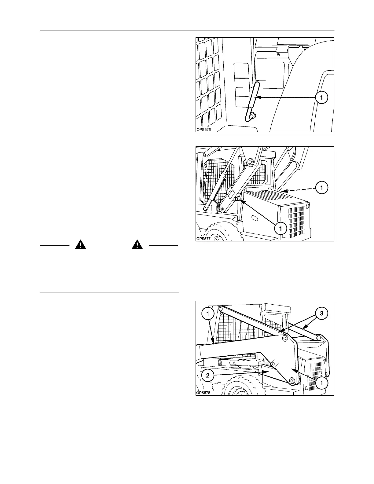
BOOM
The boom assembly consists of:
Op. 82 100 50
1 Main boom frame
Op. 82 100 52
2 Lower link, right and left
Op. 82 100 53
3 Upper link, right and left
The boom and links are supported on the ROPS main
frame with tapered pivot pins at all pivot locations.
4
 Loading...