SECTION 55 - ELECTRICAL SYSTEM
55-128
Alternator Construction
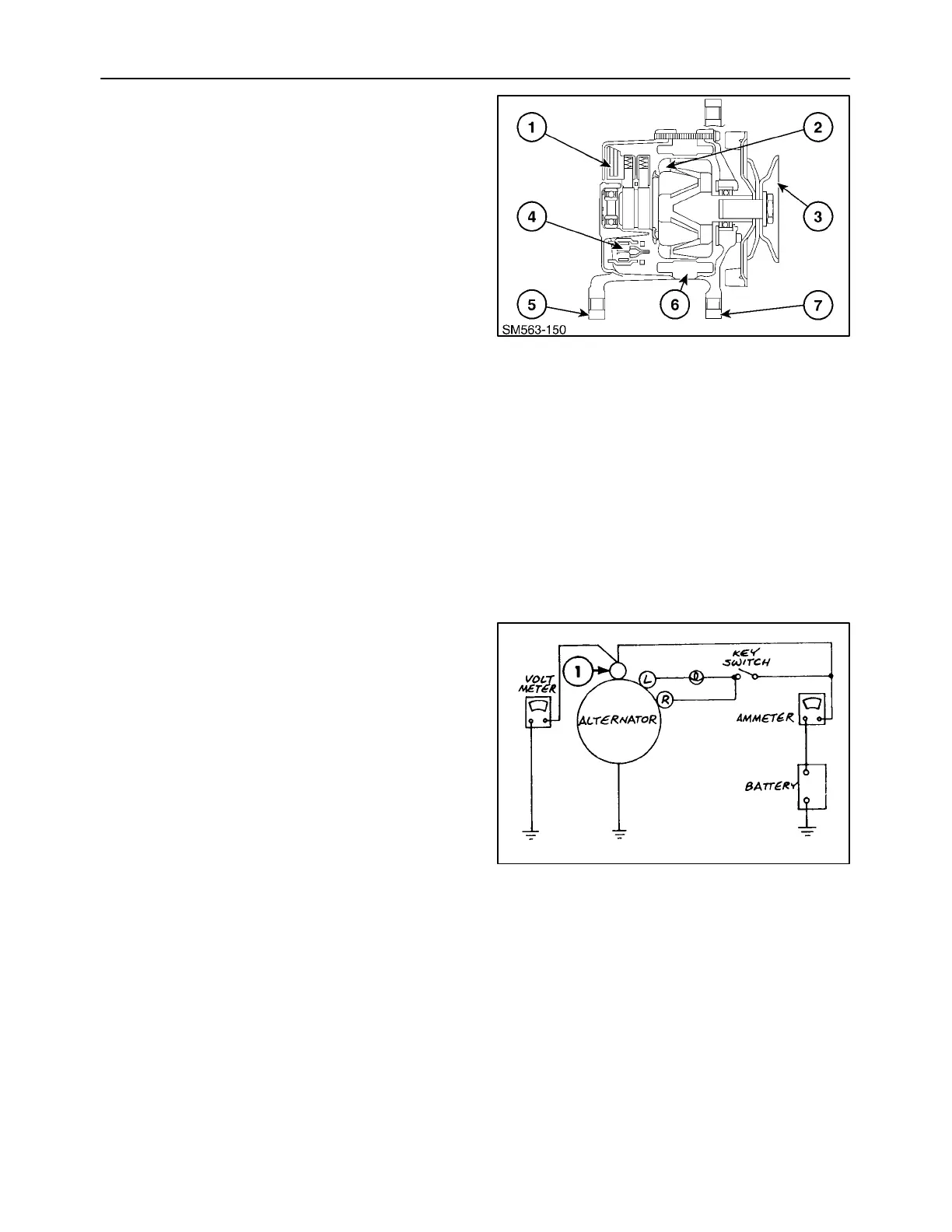
Sectional view of the IC alternator
The principal components of the IC alternator are the
stator, the rotor, the rectifier assembly, the IC voltage
regulator, the front bracket, the rear bracket, and the
pulley.
The rectifier assembly consists of two heat sinks, one
positive and one negative, and diode trio. The diode
trio is used as a field supply diode and is connected
to the field coil and terminal L on the alternator.
The built-in IC regulator is a solid-state unit so that it
can only be serviced as an assembly.
1. IC voltage regulator
2. Rotor
3. Pulley
4. Rectifier
5. Rear support bracket
6. Stator
7. Front support bracket
175
Check on the Equipment
Checking the regulator adjusting voltage.
A. In the case of equipment without an ammeter,
connect a test ammeter (50A capacity) at the
position shown.
In the case of equipment with an ammeter, make
use of the ammeter on the equipment.
B. Connect a voltmeter between terminal 1 of the
alternator and the ground.
1. In this state, confirm the reading on the voltmeter
indicates the battery voltage.
2. If the voltmeter reading is zero, the wiring
between terminal 1 and the battery is faulty.
176

 Loading...