SECTION 33 - BRAKES AND CONTROLS
33-19
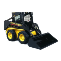
7. Install outer brake disc, 1, on motor shaft.
8. Thread caliper retaining bolts into outer section
of caliper, 2, and tighten to 70 N·m (52 ft. lbs.).
Check the center section of the caliper, 3, to
make sure it is free to move.
39
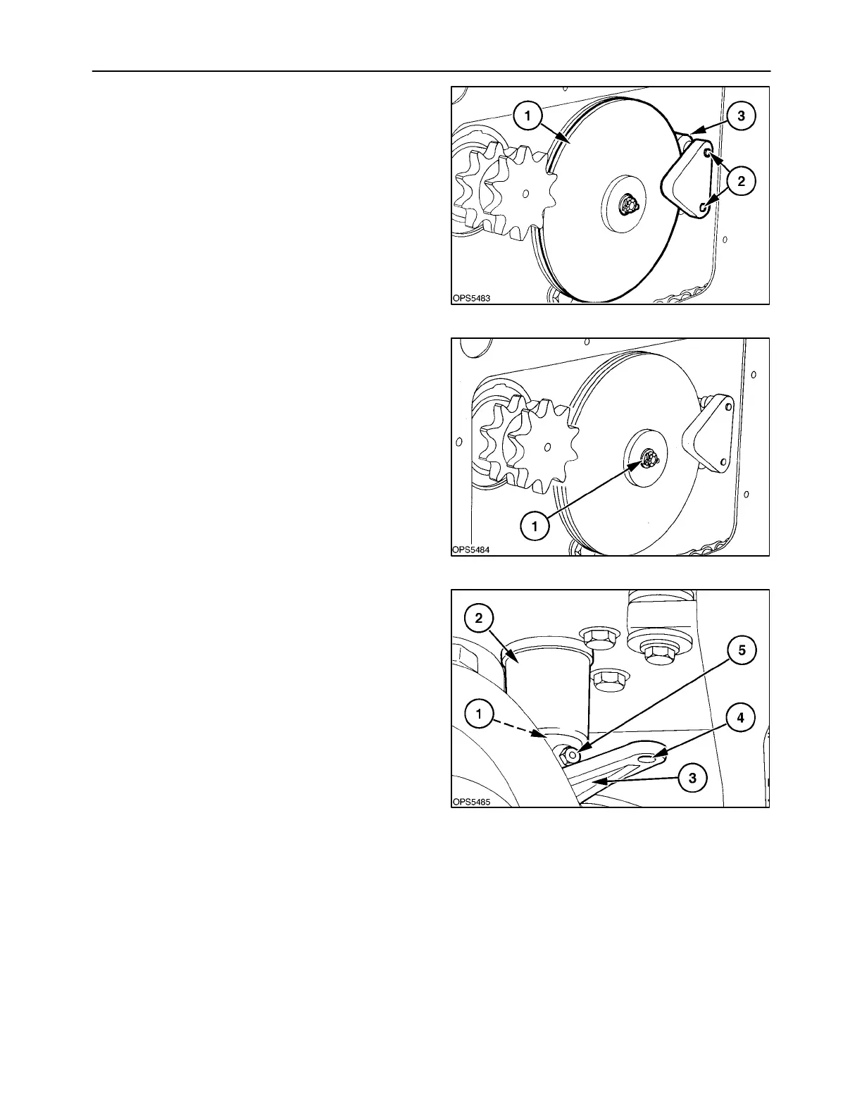
9. Put a bead of sealer on end of motor coupler and
install the brake disc retaining bolt and large flat
washer, 1. Tighten to 35 N·m (26 ft. lbs.).
40
10. Thread the shaft, 1, into the support, 2, to remove
all play in brake caliper and disc.
11. Rotate and position the control arm, 3, so the
spring link can be reconnected at 4.
– Then slide the control arm onto the shaft.
– Position the control arm on the shaft for clear-
ance between arm and other components
when the brake is engaged and disengaged.
– Tighten the retaining screw, 5, in the control
arm.
– Install cotter pin in spring link at 4.
41
 Loading...