SECTION 35 - HYDRAULIC SYSTEM
35-65
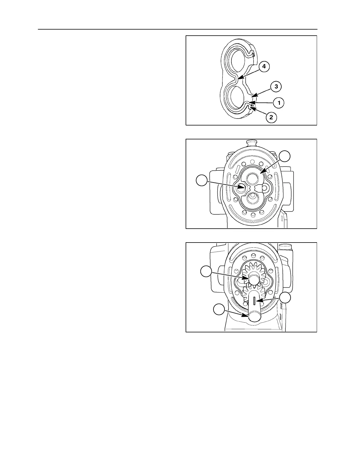
NOTE: The gasket AND seal must align and lay flat
when installed in the wear plate.
96
4. Install the wear plate assembly, 1, with the gas-
ket/seal side towards the pump mounting plate
with the mid section cut away on the suction side,
2, of the pump.
19997783
1
2
19997783
97
5. Install the drive shaft, 1, making sure to engage
the splines inside the hydrostatic pump. Install
the idler gear assembly, 2, into the bushing. Ro-
tate the gears to help slide the idler gear into
place.
NOTE: The drive shaft and gear, 1, must tbe properly
seated into the hydrostatic pump drive shaft splines
with the end of gear teeth against the wear plate.
Position the keyway, 3, up.
1
2
19997788
3
98

 Loading...