M126/M127/M128 4-76 SM
4.3.3 SCANNER ASSEMBLY REMOVAL
1. Left scanner cover ( p.4-85 "Left Scanner Cover Removal").
2. Right scanner cover (
p.4-86 "Right Scanner Cover Removal").
3. Left side cover (
p.4-26 "Left Side Cover Removal").
4. Right side cover (
p.4-66 "Right Side Cover Removal").
5. Lift the flatbed and ADF assemblies to the up position.
6. Controller board shield (
p.4-10 "Controller Board Shield").
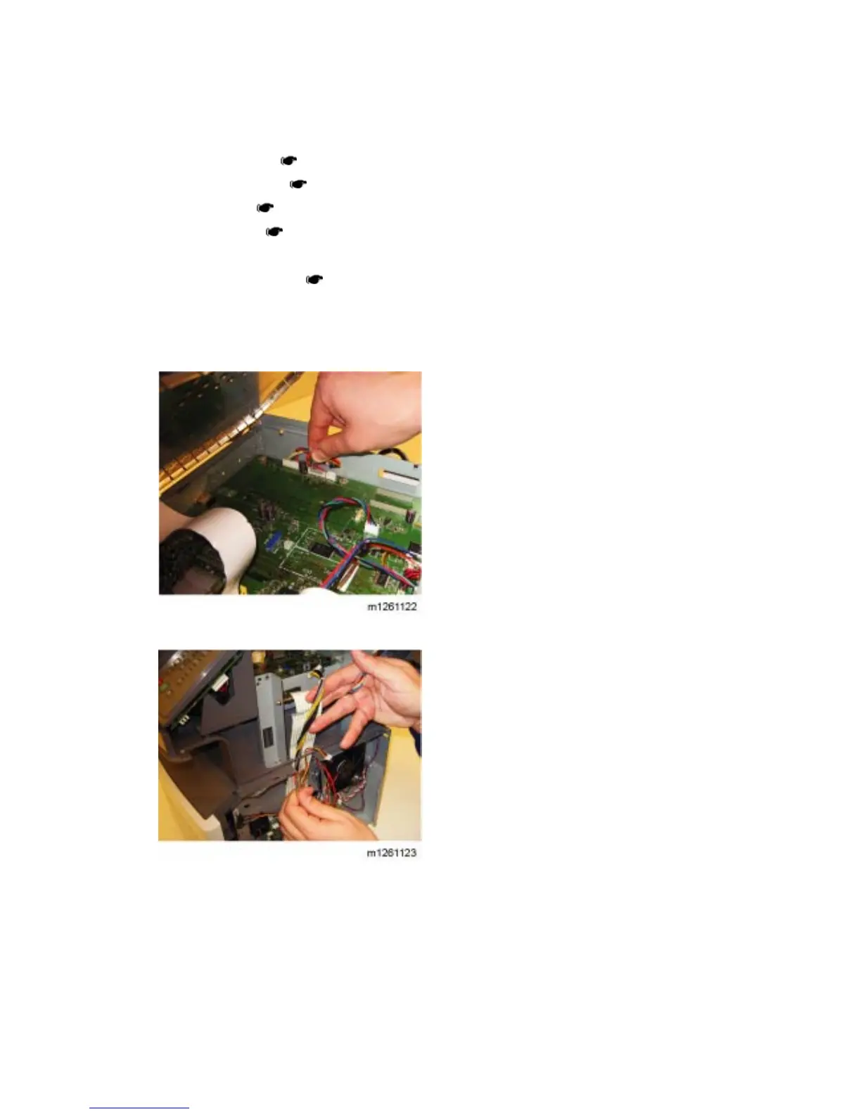
7. Disconnect the HVPS cable from connector J37 on the controller board.
8. Disconnect the front cover interlock switch cable from connector J11 on the controller board.
9. Disconnect the stairway cables from J500 and J501 on the engine board.
10. Disconnect the LSU laser diode cable from the controller board.
11. Thread the LSU diode cable, the cover interlock cable, the stairway cables, and the controller
board power supply cable through the side of the printer away from the scanner assembly.
 Loading...