6C-14 Power Assisted Steering System:
Tightening torque
Steering lower shaft bolt: 25 N·m (2.5 kgf-m, 18.5
lb-ft)
Gear case high pressure pipe union bolt: 35 N·m
(3.5 kgf-m, 25.5 lb-ft)
Gear case cylinder pipe flare nut: 25 N·m (2.5 kgf-
m, 18.0 lb-ft)
Gear case mounting bolt: 105 N·m (10.5 kgf-m, 76
lb-ft)
Gear case low pressure pipe union bolt: 40 N·m (
4.0 kgf-m, 29.0 lb-ft)
Stabilizer bar mount bracket mount bolt (a): 60
N·m (6.0 kgf-m, 43.0 lb-ft)
• After installation, be sure to fill specified P/S fluid and
bleed air. Refer to “P/S System Air Bleeding
Procedure: ”.
• Check toe setting. Adjust as required. Refer to “Front
Wheel Alignment Inspection and Adjustment: in
Section 2B”.
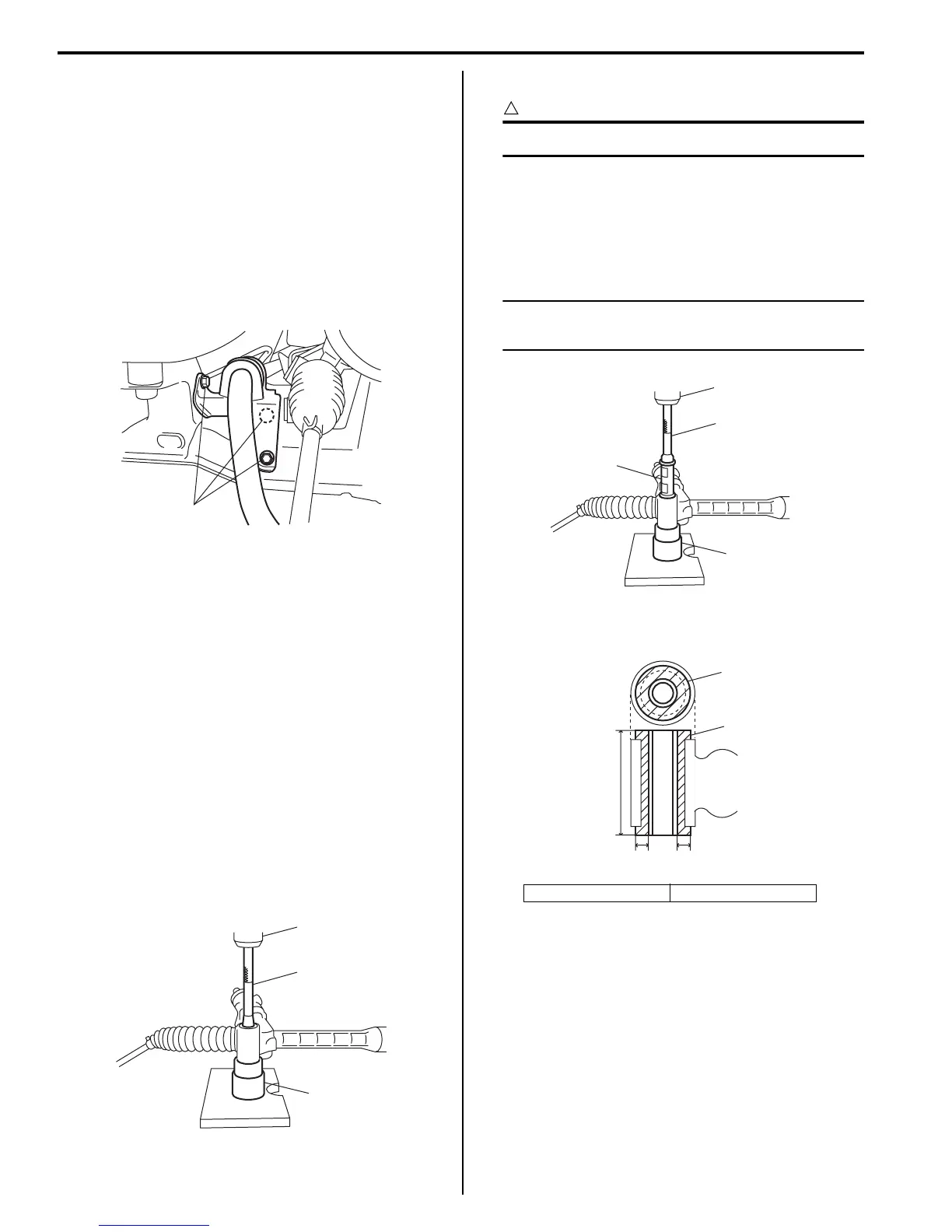
Steering Gear Case Mount Bushing Removal
and Installation
S5JB0A6306024
Removal
1) Remove P/S gear case assembly referring to “P/S
Gear Case Assembly Removal and Installation: ”.
2) Push out bushing using hydraulic press (1) and
special tools.
Special tool
(A): 09943–88211
(B): 09945–55410
Installation
CAUTION
!
Be sure to use new bushing.
1) Press-fit bushing (1) using special tools and press
(2).
Special tool
(A): 09913–75821
(B): 09945–55410
NOTE
Before installing bushing, apply soap water
on its circumference to facilitate installation.
2) Press-fit bushing (1) so that dimensions and in figure
become equal.
3) Install P/S gear case assembly referring to “P/S
Gear Case Assembly Removal and Installation: ”.
Steering Gear Case Mount Bushing Inspection
S5JB0A6306025
Inspect for looseness, cracks, deformation or damage.
Replace any defective part.
(a)
I5JB0A630021-02
(A)
1
(B)
I5JB0A630053-02
“A”: 6 mm (0.24 in.) “B”: 80 mm (3.15 in.)
(A)
2
1
(B)
I5JB0A630055-01
1
1
“B”
“A” “A”
I5JB0A630056-01

 Loading...


