5A-46 Automatic Transmission/Transaxle:
“POWER” Light Circuit Check – Light Does Not Come “ON” at Ignition Switch ON
S5JB0A5104065
Troubleshooting
DTC P0705 Transmission Range Sensor Circuit Malfunction
S5JB0A5104026
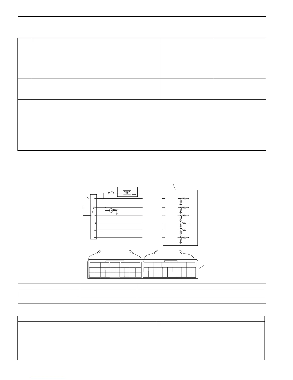
Wiring Diagram
DTC Detecting Condition and Trouble Area
Step Action Yes No
1 Combination Meter Power Supply Check
1) Turn ignition switch ON.
Does other indicator / warning lights in combination meter
comes ON?
Go to Step 2. Repair combination
meter power supply
circuit referring to
“Combination Meter
Circuit Diagram: in
Section 9C”.
2 1) TCM power and ground circuit check referring to “TCM
Power and Ground Circuit Check: ”.
Is it in good condition?
Go to Step 3. Repair or replace.
3 DTC check
1) Check DTC referring to “DTC Check: ”.
Is there DTC P1774 or P1775?
Go to applicable DTC
diag. flow.
Go to Step 4.
4 Combination Meter Function Check
1) Turn ignition switch ON.
Does A/T selector position indicator show correct select
lever position?
Replace combination
meter.
Substitute a known-
good TCM and recheck.
2
6
1
4
P
R
N
D
2
L
5
3
BLK/RED
RED
YEL/GRN
PNK/BLU
PNK/GRN
GRN/ORN
GRN/WHT
E93-20
E93-1
E93-8
E93-7
E93-19
E93-18
65
16 15 14 13 12 11
43
24 23 2122
10 9 8 7
21
1920 18 17
E92
17 16
26 25
15 14
65 342
13 12
23 2224
11 10 9
21 20 19
87
18
1
E93
7
I5JB0A510020-01
1. TCM 4. Brake light switch 7. Terminal arrangement of TCM connector (viewed from harness side)
2. Transmission range sensor
(switch)
5. Back-up light
3. From ignition switch 6. Shift lock solenoid
DTC Detecting Condition Trouble Area
Multiple signals are inputted simultaneously for 2 seconds.
(1 driving cycle detection logic)
• Select cable maladjusted.
• Transmission range sensor (switch)
maladjusted.
• Transmission range sensor (switch) or its circuit
malfunction.
•TCM

 Loading...


