Air Conditioning System: 7B-58
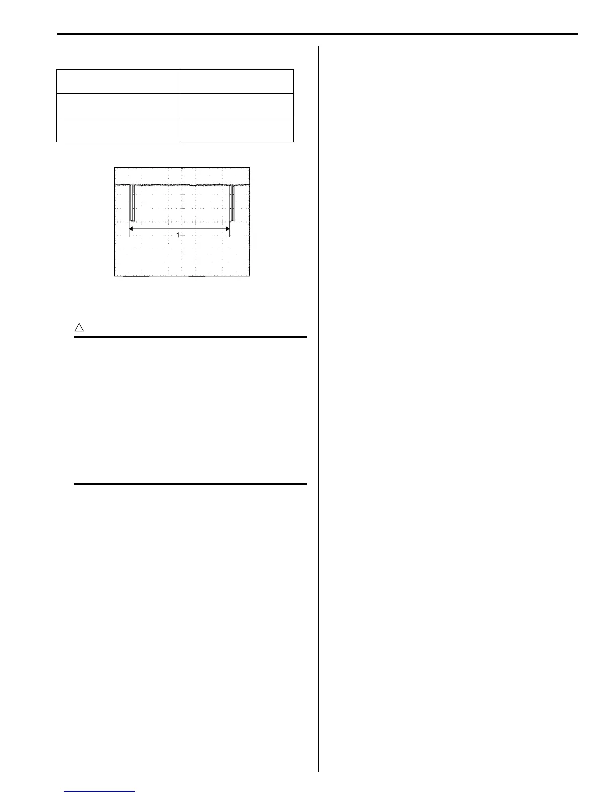
Reference waveform No. 1
Serial communication line to BCM (1)
A/C System Inspection at ECM
S5JB0A7204051
CAUTION
!
• ECM connectors are waterproofed. Each
terminal of the ECM connectors is sealed
up with the grommet. Therefore, do not
measure circuit voltage and resistance by
inserting the tester’s probe into the sealed
terminal at the harness side. Or, ECM and
its circuits may be damaged by water.
• ECM (PCM) cannot be checked by itself.
It is strictly prohibited to connect voltmeter
or ohmmeter to ECM (PCM) with couplers
disconnected from it.
Voltage Check
ECM (PCM) and its circuits can be checked at ECM
(PCM) wiring couplers by measuring voltage as follows.
Refer to “Inspection of ECM and Its Circuits: in Section
1A”.
• C37-12 A/C refrigerant pressure sensor signal
• C37-14 Output of 5 V power source
• C37-15 Ground for ECM
• C37-24 Engine coolant temp. (ECT) sensor signal
• C37-29 Ground for ECM
• C37-30 Ground for ECM
• C37-48 Ground for ECM
• C37-52 CMP sensor signal
• C37-57 Ground for sensors
• C37-58 Ground for ECM
• E23-4 CAN (high) communication line (active high
signal) to ABS control module
• E23-16 Main power supply
• E23-19 CAN (low) communication line (active low
signal) to ABS control module
• E23-46 Radiator fan relay No.1 output
• E23-47 Radiator fan relay No.2 output
• E23-48 Radiator fan relay No.3 output
• E23-49 A/C compressor relay output
Measurement terminal CH1: “G52-11” to “G52-
17”
Oscilloscope setting CH1: 5 V / DIV
TIME: 20 ms / DIV
Measurement condition Ignition switch is at ON
position
I5JB0A720091-01

 Loading...


