1A-69 Engine General Information and Diagnosis:
DTC P0037 / P0038: HO2S Heater Control Circuit Low / High (Sensor-2)
S5JB0A1104016
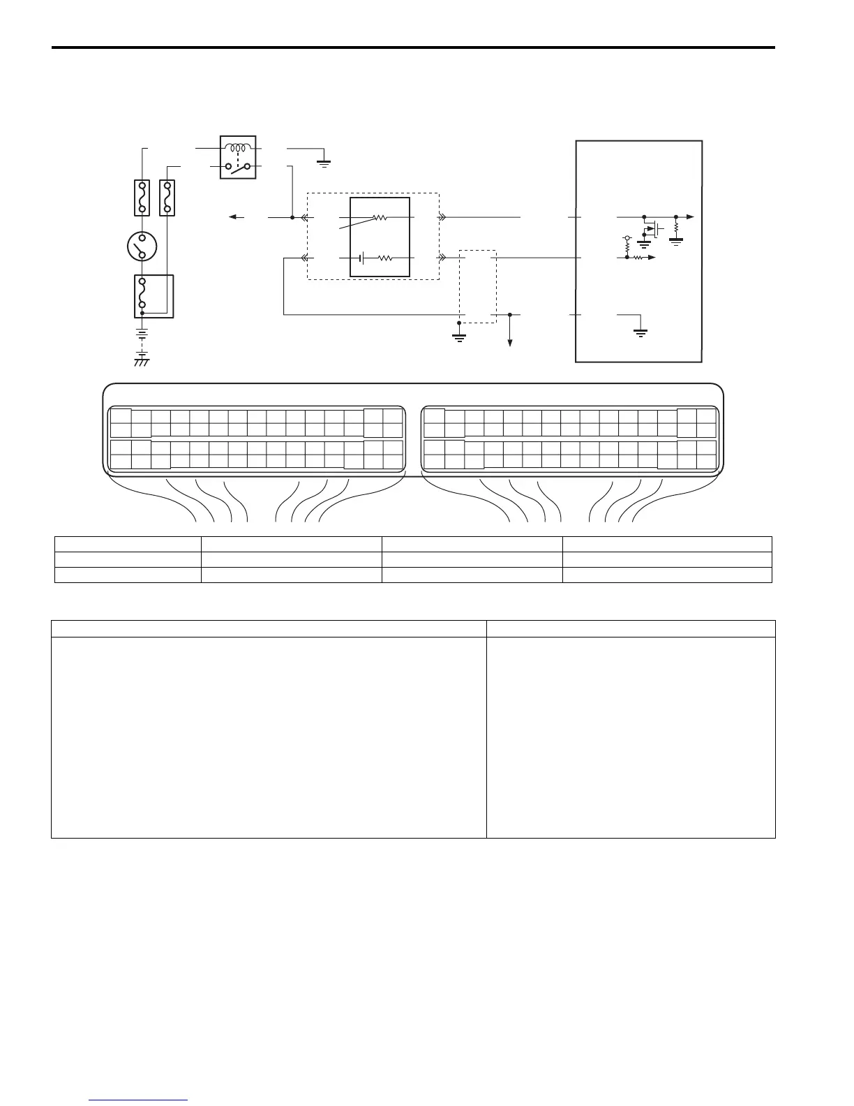
Wiring Diagram
DTC Detecting Condition and Trouble Area
DTC Confirmation Procedure
1) With ignition switch turned OFF, connect scan tool.
2) Turn ON ignition switch and clear DTC using scan tool.
3) Start engine and warm up to normal operating temperature.
4) Run engine at idle speed for 1 min.
5) Check DTC and pending DTC.
E23 C37
34
1819
5671011
1720
47 46495051
2122
52
1625
9
24
14
29
5557 54 53
59
60 58
2
262728
15
30
56 48
32 31343536374042 39 38
44
45 43 41 33
11213
23
834
1819
5671011
1720
47 46495051
2122
52
1625
9
24
14
29
5557 54 53
59
60 58
2
262728
15
30
56 48
32 31343536374042 39 38
44
45 43 41 33
11213
23
8
4
3
9
RED
GRN
PNK
BLK
C37-47
C37-11
C37-57
6
2
7
10
BLK
BLU
WHT
BLK/RED
GRY/GRN
1
8
5
5V
BLK/WHT
BLK
PNK*GRN
I5JB0A110032-01
1. HO2S heater relay 4. “O2 HTR” fuse 7. Heater 10. To other sensors
2. Shield wire 5. “IG COIL” fuse 8. To A/F sensor heater *: For M16 engine
3. Ignition switch 6. HO2S-2 9. ECM
DTC detecting condition Trouble area
P0037:
HO2S-2 circuit voltage is lower than specification for more than
specified time continuously even though control duty ratio of HO2S-2
heater is less than 75% with engine running. (Heater control duty
pulse is not detected in its monitor signal)
(2 driving cycle detection logic)
P0038:
HO2S-2 circuit voltage is higher than specification for more than
specified time continuously even though control duty ratio of HO2S-2
heater is more than 25% with engine running. (Heater control duty
pulse is not detected in its monitor signal)
(2 driving cycle detection logic)
• HO2S-2 heater
• HO2S-2 heater circuit
•ECM