4E-26 ABS:
DTC C1071: ABS Control Module
S5JB0A4504018
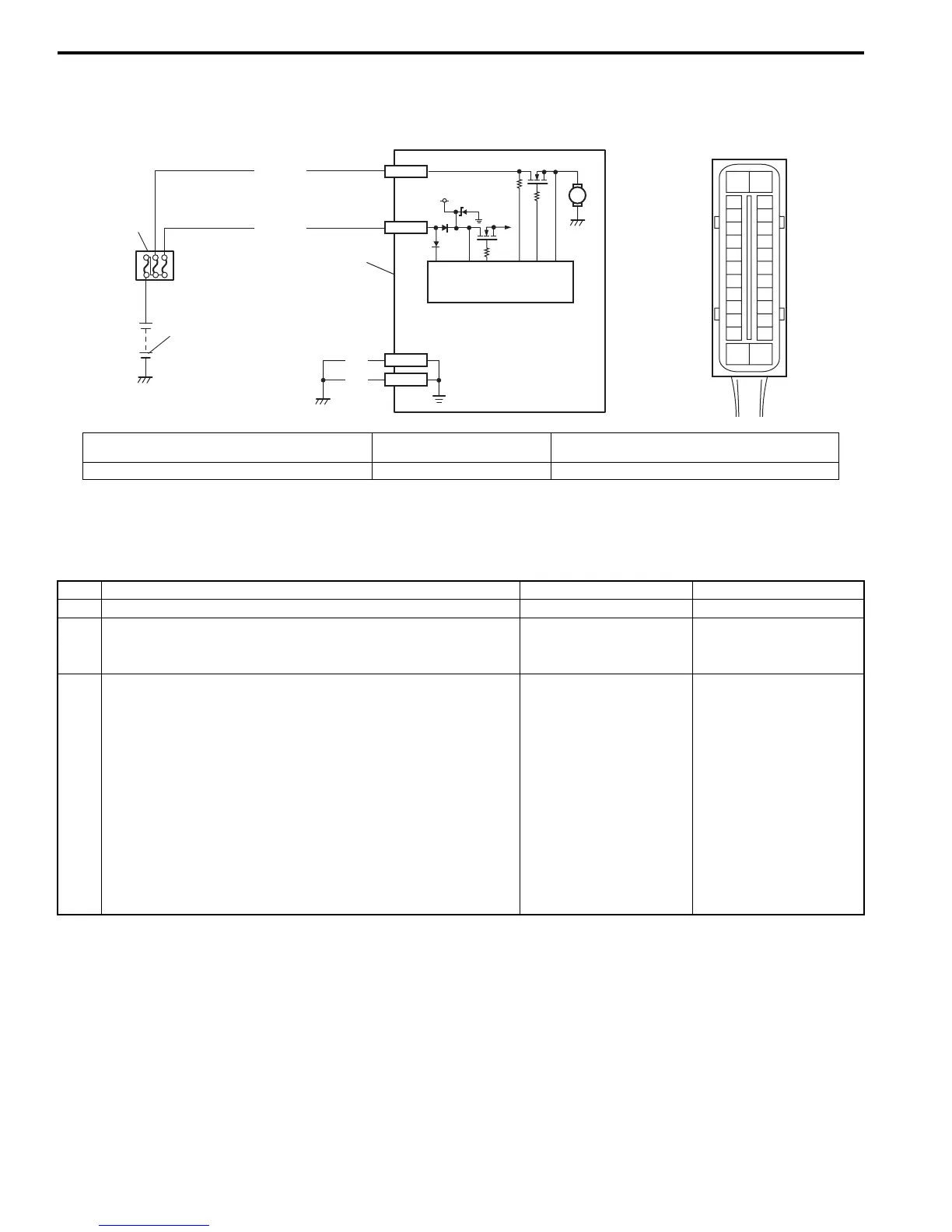
Wiring Diagram
DTC Detecting Condition
This DTC will be set when an internal malfunction is detected in the ABS control module.
DTC Troubleshooting
1
2
WHT/BLU
12V
M
3
4
E03-1
E03-14
BLK
BLK
E03-13
E03-26
WHT/RED
[A]
E03
15
16
17
18
19
20
21
22
23
24
25
2
3
4
5
6
7
8
9
10
11
12
1
13
14
26
I5JB0A450019-02
[A]: ABS hydraulic unit / control module connector
(viewed from terminal side)
2. Main fuse box 4. ABS hydraulic unit / control module assembly
1. Battery 3. ABS power control module
Step Action Yes No
1 Was “ABS Check” performed? Go to Step 2. Go to “ABS Check: ”.
2 Clear all DTCs and check DTC.
Is it DTC C1071?
Go to Step 3. Could be a temporary
malfunction of the ABS
control module.
3 1) Check for proper connection of ABS hydraulic unit /
control module connector.
2) If OK, disconnect ABS hydraulic unit / control module
connector and check the following.
• Voltage “E03-1” terminal: 10 – 14 V
• Voltage “E03-14” terminal: 10 – 14 V
• Resistance between “E03-13” and body ground:
Continuity
• Resistance between “E03-26” and body ground:
Continuity
Are the check result as specified?
Replace ABS hydraulic
unit / control module
assembly.
Repair “WHT/RED”,
“WHT/BLU” and/or
“BLK” circuit and
recheck.

 Loading...


