1A-245 Engine General Information and Diagnosis:
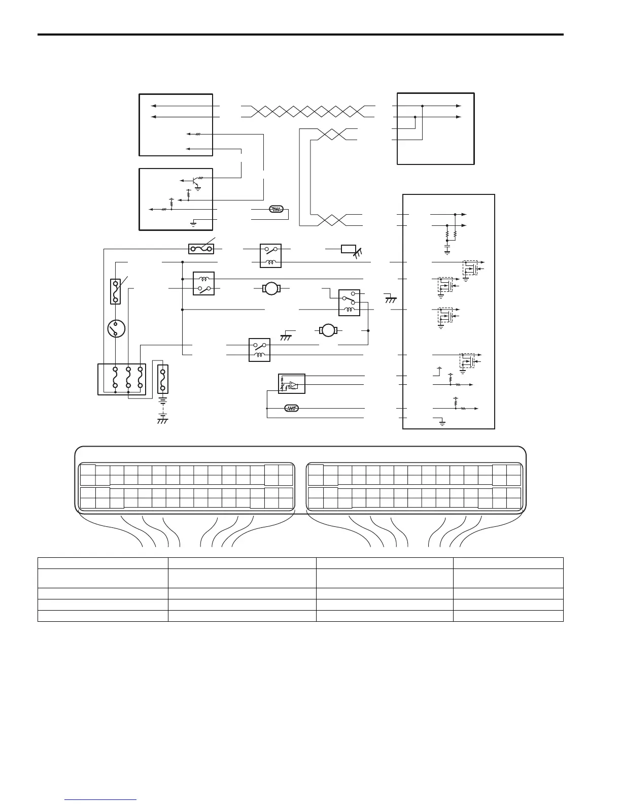
A/C System Circuits Check
S5JB0A1104069
Wiring Diagram
E23 C37
34
1819
5671011
1720
47 46495051
2122
52
1625
9
24
14
29
5557 54 53
59
60 58
2
262728
15
30
56 48
32 31343536374042 39 38
44
45 43 41 33
11213
23
834
1819
5671011
1720
47 46495051
2122
52
1625
9
24
14
29
5557 54 53
59
60 58
2
262728
15
30
56 48
32 31343536374042 39 38
44
45 43 41 33
11213
23
8
5V
RED/BLK
E23-46
E23-47
BLU/RED
BLU/YEL
BLU/BLK
E23-48
PPL/YEL
GRY/GRN
C37-24
C37-57
BLK
RED
YEL/GRN
RED/YEL
BLK
BLU
BLU
BLU/WHT
YEL/GRN
5V
WHT/BLU
WHT/RED
E23-4
E23-19
RED
WHT
WHT/BLU
WHT/RED
RED
WHT
5V
PNK/GRN
YEL/RED
WHT/BLK
BLK/RED
12V
PNK
*RED
GRY/RED
GRY/BLK
C37-14
C37-12
WHT/RED
E23-49
YEL/GRNYEL/GRN
5V
1
2
4
9
11
12
15
16
5
8
14
13
7
10
3
6
I5JB0A110103-02
1. BCM 6. “IG2 SIG” fuse 11. Radiator cooling fan relay No.2 16. ECT sensor
2. ABS hydraulic unit / control
module assembly
7. “CPRSR” fuse 12. Radiator cooling fan relay No.3 *: For M16 engine
3. HVAC control module 8. Compressor relay 13. Radiator cooling fan No.1
4. ECM 9. Compressor 14. Radiator cooling fan No.2
5. Evaporator temperature sensor 10. Radiator cooling fan relay No.1 15. A/C refrigerant pressure sensor

 Loading...


