5A-82 Automatic Transmission/Transaxle:
Manual Selector Assembly Removal and
Installation
S5JB0A5106044
Removal
1) Disconnect negative cable at battery.
2) Remove front console box.
3) Disconnect shift lever switch connector.
4) Remove manual selector assembly mounting bolts.
5) Disconnect select cable (1) from manual selector
assembly (2).
Installation
Reverse removal procedure to install manual selector
assembly noting the following instructions.
• Tighten manual selector assembly mounting bolts to
specified torque.
Tightening torque
Manual selector assembly mounting bolt: 18 N·m
(1.8 kgf-m, 13.0 lb-ft)
• Adjust select cable referring to “Select Cable
Adjustment: ”
Select Lever Knob Installation
S5JB0A5106045
Screw select lever knob onto select lever by specified
numbers of rotation below.
Rotation numbers for select lever knob
Installation (a): 13 – 14 rotations
CAUTION
!
When installing select lever knob, do not turn
more than specified numbers of rotation.
Otherwise select lever knob is damaged.
Manual Selector Assembly Inspection
S5JB0A5106046
Check select lever for smooth and clear-cut movement
individually and position indicator for correct indication.
If a malfunction is found, replace select lever assembly.
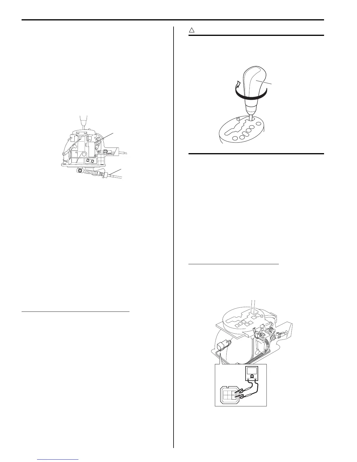
“3” Position Switch Inspection
S5JB0A5106091
1) Disconnect negative cable at battery.
2) Remove front console box.
3) Disconnect manual selector connector (1).
4) Measure resistance between “3” position switch
terminals.
“3” position switch specification
Shift selector lever to “P”, “N” or “D” range: 3.96
– 4.04 kΩ
Shift selector lever to “R”, “3”, “2” or “L” range:
0.99 – 1.01 kΩ
1
2
I5JB0A510034-02
1,(a)
I4RS0A510058-01
I5JB0A510164-01

 Loading...


