Transfer: Motor-Shift Type (Transfer with Shift Actuator) 3C-27
DTC C1213: Transfer Switch Circuit Open
S5JB0A3314041
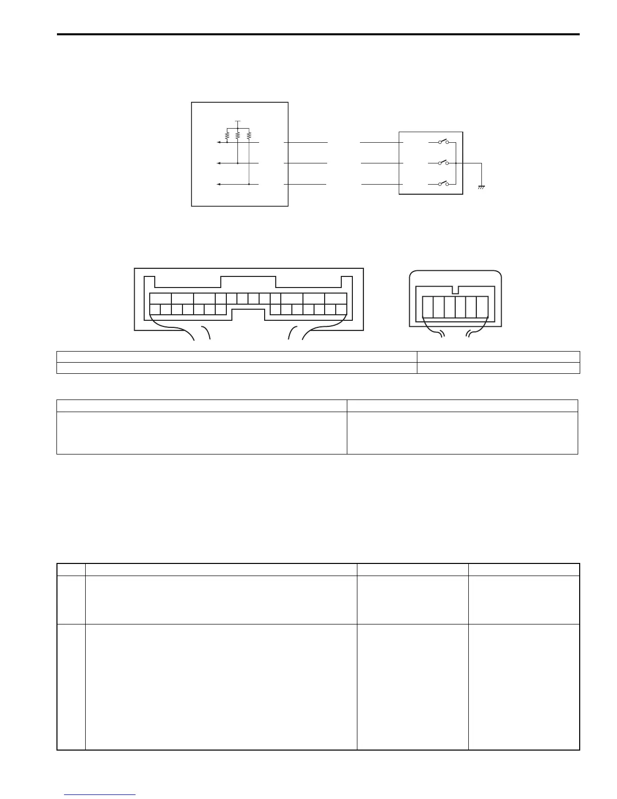
Wiring Diagram
DTC Detecting Condition and Trouble Area
DTC Confirmation Procedure
1) Clear DTC using scan tool.
2) Select transfer switch to “4H” position and keep its position for 10 seconds. Similarly select transfer switch to “4H-
lock”, “N” and “4L-lock” position.
3) Check DTC.
Troubleshooting
E91-18
E91-19
E91-20
BLU/ORN
BLU/BLK
LT GRN
1
2
12V
G59-4
G59-3
G59-2
1
2
3
45
6
7
891011
12
13
14
1516
1718
19
20
21
22
23
24
25
26
[A]
1
2
3
4
5
6
[B]
I5JB0A332016-01
[A]: 4WD control module connector “E91” (viewed from harness side) 1. 4WD control module
[B]: Transfer switch connector “G59” (viewed from harness side) 2. Transfer switch
DTC detecting condition Trouble area
Transfer switch combination different from specification is
detected for more than 0.5 seconds.
• Transfer switch
• Transfer switch circuit
• 4WD control module
Step Action Yes No
1 Was “4WD control system check” performed? Go to Step 2. Go to “4WD Control
System Check: Motor-
Shift Type (Transfer with
Shift Actuator)”.
2 Transfer switch circuit check
1) Disconnect transfer switch connector “G59” with ignition
switch OFF.
2) Check for proper connection to “G59-2”, “G59-3” and
“G59-4” terminals of transfer switch connector.
3) If connection is OK, measure voltage between “G59-2”,
“G59-3” or “G59-4” terminal of transfer switch connector
and vehicle body ground with ignition switch ON.
Is it 10 – 14 V?
Go to Step 3. Go to Step 4.

 Loading...


