6C-20 Power Assisted Steering System:
P/S Pump Assembly Components for J20
Engine Model
S5JB0A6306022
P/S Pump Disassembly and Assembly for M16
Engine Model
S5JB0A6306013
Disassembly
1) Clean its exterior thoroughly.
2) With aluminum plates placed on vise first, grip pump
body (15) with it.
3) Remove suction connector bolt, suction connector
(1) and O-ring (2) from pump body (15).
4) Remove power steering pressure switch (terminal
set) (3) from pump body (15).
5) Remove plug (6), flow control spring (5) and relief
valve (flow control valve) (4) from pump body (15).
6) Remove cover bolts, pump cover (7) and O-ring (2)
from pump body (15).
7) Remove snap ring (11) from pump shaft (13).
8) Remove vanes (9) from rotor (10).
9) Remove cam ring (8), rotor (10), side plate (12) and
O-rings (2) from pump body (15).
10) Pull out pulley (13) from pump body (15).
11) Remove oil seal (14) from pump body (15).
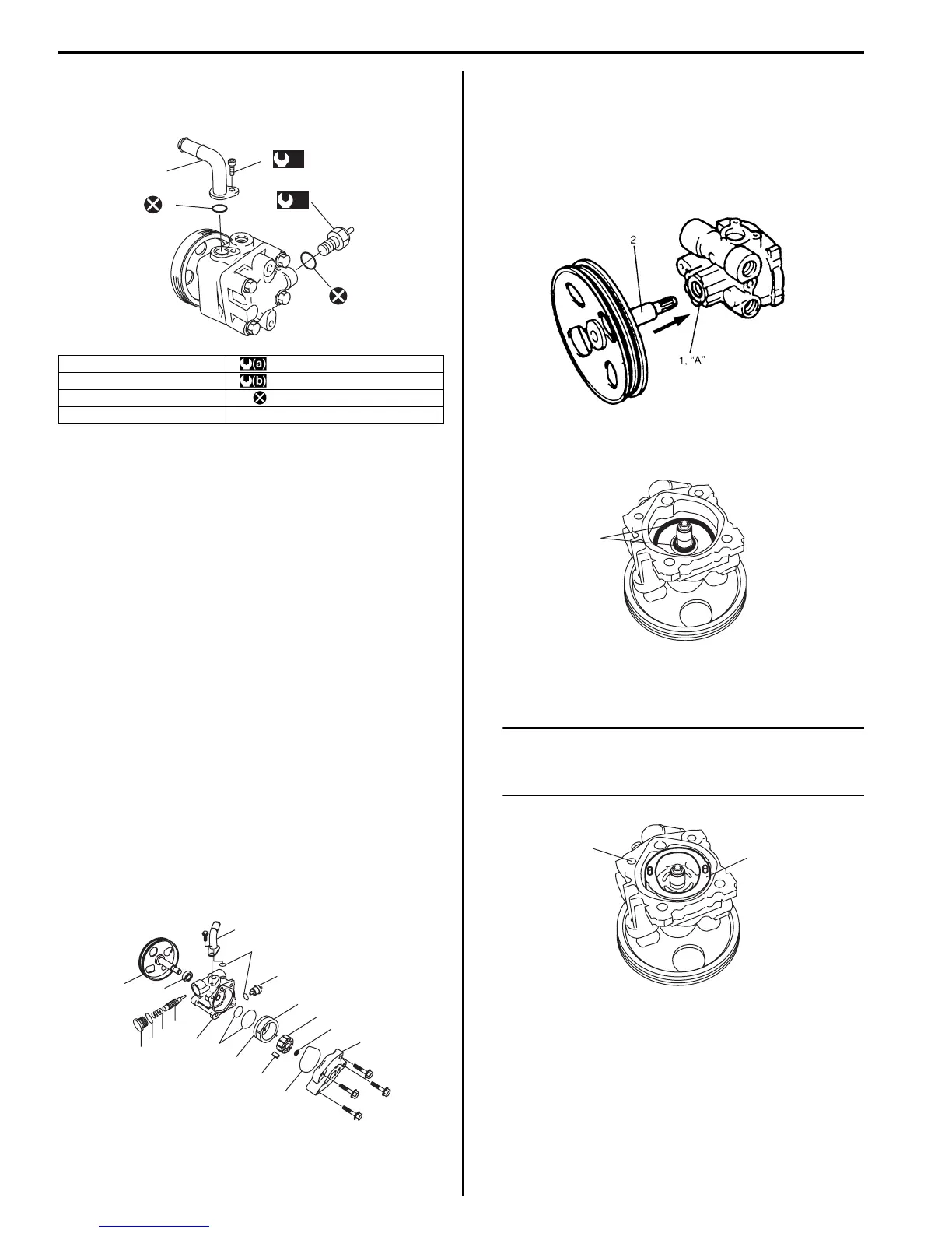
Assembly
1) Apply grease to oil seal (1) lip and apply P/S fluid to
sliding surface of the shaft (2) then insert pulley’s
shaft (2) from oil seal side of the pump body.
“A”: Grease 99000–25010 (SUZUKI Super
Grease A)
2) Apply power steering fluid to O-rings (1) and fit them
to pump body.
3) Install side plate and cam ring and side plate (1) to
pump body.
NOTE
Carefully align the dowel pins on the cam
ring and side plate (1) at bolt hole (2) as
shown in the figure.
1. Suction connector : 3.7 N⋅m (0.37 kgf-m, 2.7 lb-ft)
2. O-ring : 20 N⋅m (2.0 kgf-m, 14.5 lb-ft)
3. Pressure switch : Do not reuse.
4. Suction connector bolt
1
4
(a)
3
(b)
2
2
I5JB0A630029-03
1
13
14
6
2
5
4
15
2
12
9
2
3
8
10
11
7
2
I5JB0A630030-02
IYSQ01630041-01
1
I5JB0A630031-01
1
2
I5JB0A630032-01

 Loading...


