ABS: 4E-25
DTC C1063: Solenoid Valve Power Supply Driver Circuit
S5JB0A4504017
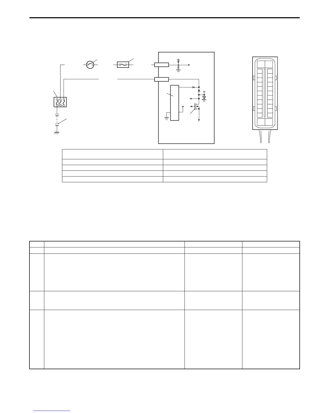
Wiring Diagram
DTC Detecting Condition
ABS control module monitors the voltage at the terminal of solenoid circuit constantly with ignition switch turned ON.
Also, immediately after ignition switch is turned ON, perform initial check as follows.
Switch solenoid valve power supply driver (transistor) in the order of OFF → ON and check if voltage changes to Low →
High. If anything faulty is found in the initial check and when the voltage is low with ignition switch turned ON, this DTC
will be set.
DTC Troubleshooting
3
4
12V
GRN/ORN
BLK/YEL
5
5V
12V
WHT/GRN
E03-7
E03-14
WHT/RED
[A]
E03
6
8
7
1
2
15
16
17
18
19
20
21
22
23
24
25
2
3
4
5
6
7
8
9
10
11
12
1
13
14
26
I5JB0A450018-02
[A]: ABS hydraulic unit / control module connector
(viewed from terminal side)
5. Solenoid valve power supply driver (transistor)
1. Battery 6. ABS hydraulic unit / control module assembly
2. Main fuse box 7. To solenoid valve
3. Ignition switch 8. ABS power control module
4. Circuit fuse box (in junction block assembly)
Step Action Yes No
1 Was “ABS Check” performed? Go to Step 2. Go to “ABS Check: ”.
2 Check battery voltage.
Is it about 11 V or higher?
Go to Step 3. Check charging system
referring to “Battery
Inspection: in Section
1J” and “Generator Test
(Undercharged Battery
Check): in Section 1J”.
3 Check main fuse for ABS solenoid and its terminal.
Is it in good condition?
Go to Step 4. Replace fuse and check
for short circuit to
ground.
4 1) Turn ignition switch to OFF position.
2) Disconnect ABS hydraulic unit / control module
connector.
3) Check for proper connection to ABS hydraulic unit /
control module at terminal “E03-14”.
4) If OK, then measure voltage between connector terminal
“E03-14” and body ground.
Is it 10 – 14 V?
Substitute a known-
good ABS hydraulic unit
/ control module
assembly and recheck.
“WHT/BLU” circuit
imperfect short to
ground.

 Loading...


