Automatic Transmission/Transaxle: 5A-53
DTC P0722 Output Speed Sensor Circuit No Signal
S5JB0A5104032
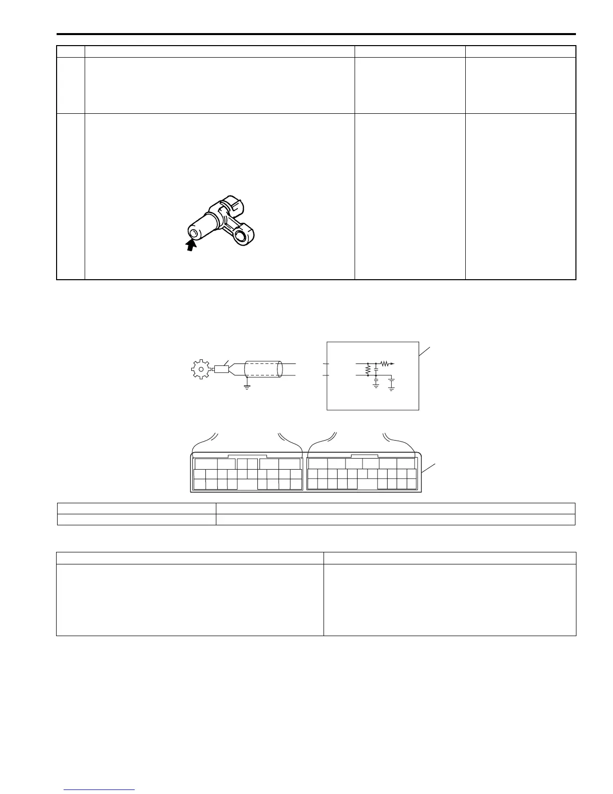
Wiring Diagram
DTC Detecting Condition and Trouble Area
DTC Confirmation Procedure
1) Connect scan tool to DLC with ignition switch OFF.
2) Clear DTCs in TCM and ECM memories by using scan tool.
3) Start engine and shift select lever to “D” range.
4) Start vehicle and increase vehicle speed to about 40 km/h (25 mile/h) for 3 minutes or more.
5) Stop vehicle.
6) Check DTC, pending DTC and freeze-frame data.
3 Inspection input shaft speed sensor
Inspect input shaft speed sensor referring to “Input Shaft
Speed Sensor Inspection: ”.
Is check result satisfactory?
Input shaft speed
sensor circuit is
malfunction.
Go to Step 4.
4 Check visually input shaft speed sensor and clutch
drum using mirror for following
• No damage
• No foreign material attached
• Correct installation
Are they in good condition?
Intermittent trouble.
Check for intermittent
trouble referring to
“Intermittent and Poor
Connection Inspection:
in Section 00”.
Clean, repair or replace.
Step Action Yes No
I2RH01510023-01
2.5V
ORN
WHT
2
1
E93-5
E93-14
65
16 15 14 13 12 11
43
24 23 2122
10 9 8 7
21
1920 18 17
E92
17 16
26 25
15 14
65 342
13 12
23 2224
11 10 9
21 20 19
87
18
1
E93
3
I5JB0A510023-01
1. TCM 3. Terminal arrangement of TCM connector (viewed from harness side)
2. Output shaft speed sensor
DTC Detecting Condition Trouble Area
No pulse signal of output shaft speed sensor is inputted for
23 pulses period of input shaft speed sensor.
(1 driving cycle detection logic)
• Output shaft speed sensor or its circuit malfunction.
• Improper output shaft speed sensor installation.
• Damaged sensor rotor.
• Foreign material attachment to sensor or rotor.
•TCM

 Loading...


