7B-11 Air Conditioning System:
Diagnostic Information and Procedures
Air Conditioning System Check
S5JB0A7204007
To ensure that system diagnosis is done accurately and smoothly, read “Precautions in Diagnosing Trouble: ” and
follow “Air Conditioning System Check: ”.
1. Outside temperature sensor 10. Blower motor 19. Alarm indicator
2. Sunload sensor 11. Blower motor controller 20. Blower speed selector / Air intake selector
3. Inside temperature sensor 12. Temperature selector / A/C switch 21. Rear defogger switch
4. ECT sensor 13. “DEF” switch 22. “REC” indicator lamp
5. Refrigerant pressure sensor 14. “DEF / FOOT” switch 23. “FRE” indicator lamp
6. Evaporator temperature sensor 15. “FOOT” switch 24. MODE selector
7. Air intake control actuator 16. “BI-LEVEL” switch 25. HVAC control module (vehicle with A/C)
8. Temperature control actuator 17. “VENT” switch 26. “DEF” indicator lamp
9. Air flow control actuator 18. “AUTO” switch
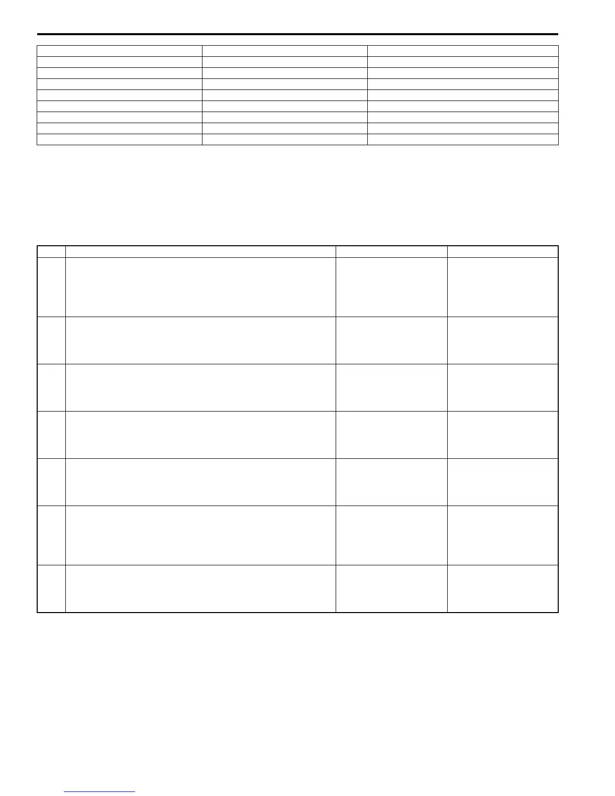
Step Action Yes No
1 ) Customer complaint analysis
1) Perform “Customer Complaint Analysis”.
Was customer complaint analysis performed according to
instruction?
Go to Step 2. Perform customer
complaint analysis.
2 ) Visual inspection
1) Perform “Visual Inspection”.
Is there any faulty condition?
Repair or replace
malfunction part.
Go to Step 3.
3 ) DTC check
1) Perform “DTC Check”.
Is it malfunction code?
Go to Step 4. Go to Step 5.
4 ) Troubleshooting for DTC
1) Check and repair according to DTC diag. flow.
Are check and repair completed?
Go to Step 7. Check and repair
malfunction part(s).
5 ) Check for intermittent problem
1) Check for intermittent problem.
Is there faulty condition?
Repair or replace
malfunction part(s).
Go to Step 6.
6 ) Air conditioning system symptom diagnosis
1) Inspect and repair referring to “A/C System Symptom
Diagnosis: ”.
Are inspect and repair complete?
Go to Step 7. Inspect and repair
malfunction part(s).
7 ) Final confirmation test
1) Perform DTC check.
Is there any DTC?
Go to Step 4. Air Conditioning system
is good condition.

 Loading...


